


In our first program , we will simply sweep the servomotor from CCW to CW and then sweep back. The program will be kept simple as to demonstrate the priniciples of controlling a servo with a the PIC Basic language. The schematic can be seen in figure 2 (below).
The variable pw controls the pulsewidth, and is started at 100 (extreme left, -45 degrees). The program sends the pulse out to the servo, and then is increased by a value of 1 until it reaches 200 (extreme right, 45 degrees), at which point it will reverese the rotation.
Listing 1
' First servomotor program
' Sweeps left to right, then reverses
Symbol B1 = pw
pw = 100
sweep: pulsout 0,pw
pause 18
pw = pw + 1
if pw > 200 then back
goto sweep
back: pulsout 0,pw
pause 18
pw = pw - 1
if pw < 100 then sweep
goto back
' create a variable pw
' start at extreme left
' send pulse to motor
' set frequency to about 50 Hz
' increase pw by 1
' at extreme right, turn CCW
' otherwise, continue
' send pulse to motor
' set frequency to about 50 Hz
' decrease pw by 1
' at extreme left, turn CW
' otherwise, continue
End of Listing 1
If desired, we could extend the rotation of the servomotor to a full 180 degrees (-90 to 90 degrees) rotation by decreasing the minimum pulsewidth to below 1 ms and increasing the maximum pulsewidth to over 2 ms. This can be accomplished with our previous program by modifying the occurances of 100 and 200 to your desired minimum and maximum pulsewidths, respectivly.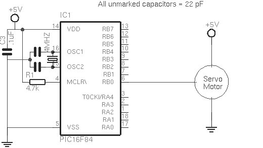
However, a note of caution: the pulsewidth required for servos varies from brand to brand. One motor may require a 2.8 ms pulsewidth for maximum rotation, while another may only need 2.4 ms.
Furthermore, servomotors have end stops that limit its rotation. If you send the motor a pulsewidth that is beyond the end stops, the motor will keep trying to turn. A motor in this stalled condition not only draws more current, but also puts wear on the internal gears, shortening the lifespan of the motor.
For more detail: First Servomotor Control Program
Related projects
Real-Time CAN-Based Vehicle Monitoring System with PIC MCU
INTRODUCTION The Controller Area Network (CAN) is a robust vehicle communication bus standard that was primarily developed for automobile applications but has...
Motors & RoboticsEasy Way to Learn Robotics Using Microcontrollers: A Beginner’s Guide
The title, "Easy Way to Learn Robotics Using Microcontrollers," promises an accessible entry point for those curious about the exciting world of...
Motors & Robotics · PIC16F877AEfficient Sun-Following Robot: A Solar Tracker with Microcontroller Control
Abstract The impending global challenge of dwindling non-renewable fuel resources underscores the urgency of transitioning towards renewable energy alternatives like solar power....
Motors & RoboticsInnovative Robotics: A Comprehensive Project Exploration
A DC motor functions as an electromechanical device, translating electrical signals into mechanical movements. The rotation of the motor correlates directly with...
Motors & RoboticsAdvanced Techniques for Fault Detection, Indication, and Protection in Induction Motors
1. INTRODUCTION The impact of microcontroller usage on our daily lives is remarkable. This versatile device is now prevalent in various control...
Motors & RoboticsExploring Versatility: GSM-Based Robotic Vehicle Technology
Introduction To Robotics The term 'Robot' remains elusive, defying a precise definition due to its evolving usage. Initially, it referred to humanoid...

Ibrar Ayyub
I am an experienced technical writer holding a Master's degree in computer science from BZU Multan, Pakistan University. With a background spanning various industries, particularly in home automation and engineering, I have honed my skills in crafting clear and concise content. Proficient in leveraging infographics and diagrams, I strive to simplify complex concepts for readers. My strength lies in thorough...