Summary of How to make(build) a Calculator using Pic16f877 microcontroller
The project describes a 2-digit calculator using the PIC16F877 microcontroller, interfaced with a 16x2 LCD and a 4x4 keypad. It performs basic arithmetic operations (addition, subtraction, multiplication, division) on single-digit numbers. Users input numbers and operators through the keypad, and results display on the LCD. The project involves configuring microcontroller ports to connect with the LCD and keypad, using a 20MHz crystal oscillator, and programming in C with the High-Tech C compiler.
Parts used in the Calculator with Pic16f877 Microcontroller:
- PIC16F877 Microcontroller
- 16x2 LCD Display
- 4x4 Keypad
- 20MHz Crystal Oscillator
- Potentiometer (for LCD contrast adjustment)
- Breadboard or PCB (for circuit assembly)
- Power Supply (5V)
alculator with Pic 16f877 microcontroller is a comprehensive project. Comprehensive in the way that Code is lengthy and logical. It covers all the aspects of programming and interfacing of 16×2 lcd and 4×4 keypad with pic Microcontrollers. So you should be good in programming, if you are going to look at the code and you should also be in good know how about how to interface 16×2 lcd and 4×4 keypad with microcontrollers.
Calculator is a 2-Digit calculator. Four functions Addition, Subtraction, Multiplication and Division(+,-,/,*) can be perfomed on single digit numbers using this calculator. User Inputs the numbers using 4×4 keypad. Result is displayed on the 16×2 lcd.
When you turn on the system. A message will be displayed on the lcd “Enter First No = “. You enter the number. Then a second message will be displayed asking you to “Enter Operator = “. You entered the operator. Then a third message will prompt up saying “Enter Second No= “. You entered the second number. As soon as you entered the second number. Fourth message will be displayed on lcd showing result of you inputs.
 Project Requirements
- Pic 16f877 Microcontroller
- 16×2 lcd
- 4×4 keypad
- Crystal 20MHz
- Potentiometer (For setting Lcd Contrast)
- Bread board or PCB for Circuit Designing
- Power Supply
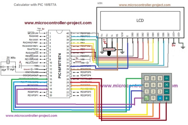
Lcd data pins are connected to Port-B of PIC 16f877 Microcontroller. Lcd Controlling pins RS(Register Select) and EN(Enable) are connecte to Port-D Pin# 6 & 7. Keypad is interfaced with Port-C of Microcontroller. Rows of Keypad are connected to Lower Nibble of Port-C. Coloumbs are connected to upper Nibble of Port-C. Apply 5 volts at VDD & VCC Pins of microcontroller and lcd. Ground VSS Pins of microcontroller and Lcd. Crystal is connected to Pin# 13 & 14 of PIC 16f877 microcontroller.
Code portion is little bit difficult. But if you are familiar with syntax of C++ Language and did some good work in c++ then the code below is easy for you to understand and to modify. First htc.h header file is included in the project. This header file must be included in every project that is using HIGH-TECH C compiler for compiling the code. Since i am using HIGH-TECH C compiler so i included it. Then the statement _XTAL_FREQ 20e6 is defining our Crystal frequency. Which is 20MHz. Next i defined Port-C & D Pins for lcd and keypad. Each port pin is also given a meaning-ful name. After that some functions are defined. Then some strings are defined. These strings are displyed on lcd. They ask the user for input and show results.
Functions
void main()
Main Function the heart of the software. Main function executes first. All other functions executes after it.
void lcdcmd (unsigned char)
This function sends commands and controls lcds registers to execute the command properly.
void lcddata (unsigned char)
This function sends data to lcd and controls lcds registers to display data on lcd.
void disp_num(float num)
This function displays calculated value on lcd efficently.
int get_num (char ch)
This function converts character value to integer.
void lcdinit ()
This function initializes the lcd. 16×2 lcd, Font-size 7×5, Cursor Blinking.
char scan_key(void)
This functions checks which keypad key is pressed by the user.
Each and every Statment of the code is well commented. Go through the code and if you feel any problem in any statement just leave your queries in the comments section below.
 Project Code
Download the project code from the links given at the bottom of the Post.
#include< htc.h>
#define _XTAL_FREQ 20e6
#define rs RD6
#define en RD7
#define r0 RC0
#define r1 RC1
#define r2 RC2
#define r3 RC3
#define c0 RC4
#define c1 RC5
#define c2 RC6
#define c3 RC7
void lcdcmd  (unsigned char);
void lcddata (unsigned char);
void disp_num(float num);
int get_num  (char ch);
void lcdinit ();
char scan_key(void);
unsigned char  s[]={"ENTER 1 NO= "};
unsigned char s1[]={"ENTER 2 NO= "};
unsigned char s2[]={"OPERATOR = "};
unsigned char s3[]={"***RESULT***"};

void lcdinit(){ __delay_ms(400);lcdcmd(0x30);	__delay_ms(400);lcdcmd(0x30);
__delay_ms(400);	lcdcmd(0x30);	__delay_ms(400);	lcdcmd(0x38);
lcdcmd(0x0F); lcdcmd(0x01); lcdcmd(0x06); lcdcmd(0x80);}Source : How to make(build) a Calculator using Pic16f877 microcontroller