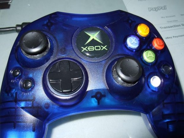
In this tutorial I show you step-by-step how I install a PIC microcontroller inside of an Xbox controller in order to provide custom functions. Now that you have the methods, all you have to do is go write some code and program a chip! Well, I know this is easier said than done, but check out my “5 transistor PIC programmer” if you are ready to go down that road.
Step 1: Tools
a small phillips screwdriver
soldering iron
solder (60/40 or 63/37… not the lead-free silver solder)
flux (this is more or less a must-have to get good connection to pcb traces)
glue gun
30 AWG wrapping wire
wire wrap tool (Optional, but makes things easier)
wire stripper (A razorblade works well on wrapping wire, but check out my instructional on “precision wire stripper” to see the one I use in this tutorial.
A DIP microcontroller
A small tactile switch
Step 2: Locate and remove the screws
Step 3: Voiding the warranty
Step 4: Remove the bottom half
Step 5: Remove the board
Now, pull up on the plastic bit that holds the headset and other peripherals. It will slide out, along with the pcb. Be mindful of the rumble motors that are still plugged into the pcb. We’ll disconnect these in a later step.
Now that you have removed the pcb, store the top half in a safe place, where you won’t lose any buttons. If they do fall out, putting them back is pretty easy. They all have unique shapes, and they can’t be put in the wrong hole.
Step 6: Back to the PCB
Step 7: Motors
Step 8: Communicator socket
Step 9: Where to put the chip
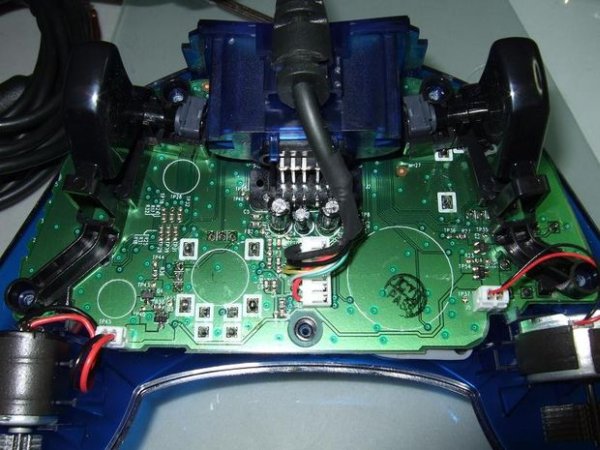
First notice the white circles? These circles show where the support cylinders on the bottom plastic contact the board. We don’t want any wires to cross these lines.
There is room enough to place a small microcontroller here. The trick is to “dead bug” it. This means we are going to place the chip upside down, and affix it to the pcb with hotmelt glue.
Step 10: Closer look
Here’s a closer look at the area highlighted in the previous picture. Notice the proximity to accessible ground and power points, as well as one of the signal traces that I was interested in for this project, namely the trace that carries the signal from the Y button to the main Atmel microcontroller that is the “brain” of this particular controller.
Look carefully for the yellow highligted boxes that show the Y-button and X-button access points.
Step 11: FYI
Step 12: Dead bug
Step 13: Give it some juice
The Atmel “brain” runs on 5V, as is common with many other microcontrollers, including our PIC, so we just have to find a good place to commandeer. I chose to take power and ground from the peripheral port. Why don’t I use that closer ground point I highlighted earlier? Well, both points are in continuity, but that’s not the whole story. Capacitance at each point may be different, and I don’t want to take any other components on the board out of their specified operating parameter in this regard, especially the precision pots nearby that provide the R thumstick inputs.
So first, apply a dab of solder to the ground lead, highlighted here.
Step 14: Prep your wire
I am using teflon insulated wire. About the only thing that will strip it (that doesn’t cost 50+ dollars) is a very sharp knife or razor blade. I posted a short instructional on my homemade stripper, which you can find by searching for “precision wire stripper.”
Step 15: Solder
Step 16: Wire wrap
Wire wrapping provides a very durable and reliable connection. I have read that is it more reliable than soldering, even, especially where the connection will be exposed to vibration. To do a good wire wrap, you should have one rotation of insulated wire followed by seven rotations of bare wire. You can also solder this connection, if you don’t have a wire wrap tool. (You can buy the tool I use from Rad shack online store for 7 dollars.)
For future reference, this is pin 8, because the chip is upside down.
Step 17: Next step
For more detail: Hacking the Xbox CONTROLLER