Summary of NES Controller iPod Remote
This article details converting an NES controller into an iPod remote using a dsPIC30F2011 microcontroller. The project involves modifying the controller's PCB to house the chip and sockets, rewiring button inputs to the PIC, and connecting the output to an iPod's remote jack or breakout board. This hack allows original Apple iPod remotes (3rd/4th Gen) or newer models with dock connectors to be controlled via a classic gamepad.
Parts used in the NES Controller iPod Remote:
- dsPIC30F2011 Microcontroller
- Microchip ICD2 Programmer (or homemade JDM Programmer)
- 8-pin DIP sockets (two 8-pin or one 16/18 pin)
- NES Controller
- Dremel with cutting bit
- Sharp knife
- Soldering iron and small gauge electrical solder
- Desoldering pump
- Flush cutters or wire cutters
- Needlenose pliers
- Standard Ethernet (CAT-5) cabling
- Small gauge wire
- 3G or 4G iPod
- Plug for the remote jack on the iPod
By embedding a PIC microcontroller into an NES controller, it can be converted into a replacement for Apple’s iPod remote.
(Only 3rd and 4th Generation iPods have this, it is a the small oval port next to the headphone jack).
Update (8/26/2011):
It’s been quite some time since iPods have used this iPod remote connector, but the dock connector (the one used on all iPods except the shuffle, iPad, and iPhone) has the same Rx/Tx pins, as well as a 3.3V out. A simple breakout board can replace the hacked connector at the end, and you can get this to work with any recent Apple products. You can buy breakout boards at: http://www.kineteka.com/PodBreakout-v1.aspx
(The mini one is pretty nice, and they also have pinout information).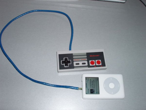
Step 1: Parts
Microcontroller- dsPIC30F2011 These can be sampled from Microchip’s sample site
Programmer- the drawback to using a dsPIC is the complicated programming procedure. The easiest way to program it is to use a Microchip ICD2, however these run fairly expensive. I have not tried this, but apparently the utilities found at http://homerreid.ath.cx/misc/dspicprg/ can be used with a homemade JDM Programmer.
IC sockets- I used 2 8-pin DIP sockets(a single 18 pin or 16 pin would have also worked). These are necessary for removing and replacing the IC for programming and debugging.
NES Controller
Dremel with a cutting bit
Sharp knife
Soldering iron and small gauge electrical solder
Desoldering pump
Flush cutters, or wire cutters
Needlenose pliers
Standard Ethernet (CAT-5) cabling
A good amount of small gauge wire- I used the innards of extra CAT-5 cable.
3G or 4G iPod.
A plug for the remote jack on the iPod. This is the most difficult to acquire. Several suggestions are made at iPod Linux’s site.
I used a small piece of a shattered old memory module that perfectly fit the remote plug, but any of the other solutions also work.
Step 2: NES Controller Prep
Unscrew the controller with a small Phillips head screwdriver, and remove the PCB. The only components that need to be added are the PIC and the sockets to hold it. This way the original look and feel of the controller is completely uncompromised.
First, the NES chip must be removed. If you do not have a desoldering pump, then the IC can be cut off the board with flush cutters, and the pins can be removed with by heating them with a soldering iron, and pulling them out with pliers.
The original NES cable also must be desoldered from the board in a similar manner.
In order to make room for the PIC, a small portion of the board must be cut away from the top-right corner. Only just enough to allow the IC in the socket to sit across the board inside the controller case should be removed. Carefully use the dremel to cut away a section about .25″ by 1″.
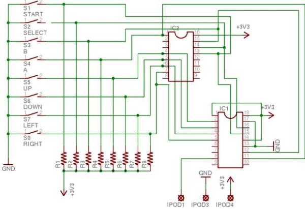
Step 3: Schematic
Step 4: Wiring the Sockets
Because of the simplicity of the idea, the only electrical work that needs to be done is attaching the IC sockets to the board, and the controller cable to the board.
The wiring of the controller is very simple in theory, but is complicated by the usage of all original components (the black lines covered with green transparent tape are, in fact, pull-up resistors.)
Much of the wiring can vary based on how much of the board was removed with the dremel. Some of the traces that were cut must be replaced with wire, especially any that connect to the button pads or the pullup resistors.
Note: the pads for the old NES chip are counted counter-clockwise from the notch printed on the back of the controller. PIC pin numbers are counted in the same way.
The colors refer to the colors of the original NES cable wires, and are printed on the back of the board (not the colors in the parenthesis).
PIC pin 1 (Master Reset) --- V+ (NES pin 16)PIC pin 2 (IO 0) --- UP (NES pin 4)PIC pin 3 (IO 1) --- DOWN (NES pin 5)PIC pin 4 (IO 2) --- LEFT (NES pin 6)PIC pin 5 (IO 3) --- RIGHT (NES pin 7)PIC pin 8 (Transmit) --- yellowPIC pin 11 (IO 4) --- A (NES pin 1)PIC pin 12 (IO 5) --- B (NES pin 15)PIC pin 13 (VSS) --- ground (The empty pad near the top right corner that is farther away from the edge)PIC pin 14 (VDD) --- V+PIC pin 15 (IO 7) --- SELECT (NES pin 13)PIC pin 16 (IO 6) --- START (NES pin 14)PIC pin 17 (AVSS) --- ground (Same empty pad as above)PIC pin 18 (AVDD) --- V+
For more detail: NES Controller iPod Remote
- Which iPod generations originally supported this remote connector?
Only 3rd and 4th Generation iPods have the small oval port next to the headphone jack. - Can this project work with newer Apple products?
Yes, because the dock connector has the same Rx/Tx pins and 3.3V out as the old remote jack. - What is the most difficult part of acquiring components for this project?
Acquiring a plug for the remote jack on the iPod is described as the most difficult to acquire. - How do you remove the original NES chip if you lack a desoldering pump?
You can cut the IC off the board with flush cutters and pull the pins out by heating them with a soldering iron. - What tool is used to cut away a portion of the board for the PIC?
A Dremel with a cutting bit is used to carefully cut away a section about .25 inch by 1 inch. - How are PIC pin numbers counted relative to the board markings?
PIC pin numbers are counted counter-clockwise from the notch printed on the back of the controller. - What alternative solution is suggested for the remote jack plug?
The author used a small piece of a shattered old memory module that perfectly fit the remote plug. - Why are two 8-pin DIP sockets necessary?
They are necessary for removing and replacing the IC for programming and debugging.