The idea of this project is to design and implement two channels EMG signal controlled video game. The player controlls the motion of the ball to the left or to the right to avoid the descending obstacles. Electrods will be placed to the back of the player’s hands to measure the voltage difference of the muscles when squeezing the hands. The signal will be filtered by a bandpass filter and amplified before sending to the ADC channels of the PIC32 microcontroller. A valid hand motion will allow the player to move the ball to interact with the game.
High Level Design
Rationale and Inspiration
Electromyography (EMG) is the measurement of muscle activation via electric potential. EMG has wide range of applications in medical research, robotic controls and other fields. The inspiration of the project came from an interest in EMG signals. I want to better understand the signals generated by our muscles while making varies gestures, and use the signal for video game control and create a unique gaming experience.
Overview
![]()
The amplitude of EMG range from 0 to 10 mV prior to amplification, and the frequency range from 5Hz to 500Hz, while the dominant signals are around 10Hz to 150Hz. The bandpass filter is designed to low pass below 500Hz and high pass above 10Hz signal since very few signals exceeding this range, and the gain is set to 100. The amplified and filtered signal is then passed into analog to digital converters on the PIC32 microcontroller. The ADC is set to sample signal at the frequency of 2000Hz. Each channel is read at 1000Hz which is more than enough to avoid aliasing.
The EMG signal level varies from person to person, and slight change in position of the electrode will change the reading of the signal. Therefore calibrating and offset the signal at the same level prior to starting the game is essential to signal detection. The games starts with 10 seconds of calibration, when the calibration is done, the game interface will be displayed automatically and the players can start moving the ball around by making a fist.
Hardware Design
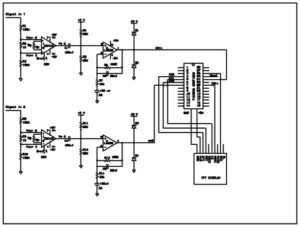
The circuit schematic is shown below. The INA121 chip is a differential amplifier which will measure the differences between the two electrodes placed on the player’s muscle. The gain is set to 10 at this stage,
gain = 1+50ohm/Rg, where Rg = 5k ohm
The gain in next stage is also set to 10,
gain = R6/R7 = R13/R14, R6 = R13 = 100k ohm, R7 = R14 = 10k ohm.
Therefore overall gain of 100 is achieved, EMG signal will be amplified up to +/- 1 V. Since the ADC input range of the microController is from 0 to 3V, the measured signal will be centered at 1.5V before sent to the next stage.
The video shows successful implement of the hardware reading input in the desired range. A sine wave swiping from 1Hz to 520Hz generated by a function generator is inputted to the circuit and plotted on TFT display. The TFT display is divided into three windows and each window display approximately 1 second of the signal.
The following two videos shows EMG signals measured at wrist and at forearm. There is significant change in the signal when the hand is moving. The signal amplitude and rise/falling time of the signal changes depend on where the electrode is placed, and the gesture, however the pattern of the change is left unknown.
Schematic
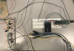
Hardware Setup
Software Design
ADC
The signals at the output of the amplifiers are fed to AN11 and AN5 of the MicroController. The clock prescalar is set to 256 to lower the clock frequency. Each channel is sampled at 1000Hz, and ADC is configured to auto sample and convert. All this is setup in the initial configuration of the ADC. The data is then smoothen out by a low pass filter that average over 100 samples.
y(n) = a*x(n)+(1-a)*y(n-1) a=0.1
When a is sent to a lower number, for example a=0.01, 1000 data will be averaged to generate the next data point. The signal will be smoother as a decreases, however it takes much longer to compute. a=0.1 is the ideal value in this application, which lowered the noise to make the signal easier for detection, and also fast enough to reflect hand motion without noticeable delay.
Valid Motion
A hand motion is considered as a valid movement if the generated EMG pulse is above the threshold for certain amount of time. The signals from both channel are plotted at the left side of the display for debugging purpose. The video below shows the signal waveform and movement count.
Before Implementing FSM
The electrodes are placed on the back of the player’s hands to detect finger movements. The count number went up when the fingers moved, however the ratio was not one to one. Apparently only considering the pulse amplitude and pulse width is not enough for accurate motion detection. A four state Finite State Machine (FSM) is necessary for debounce.
Source: EMG Signal Controlled Game