This project is one another thermometer application that uses the TCN75A digital sensor from Microchip. The sensor provides digital temp conversion in the range -40°C – 125°C (-40°F – 257°F) and has maximum resolution 0.0625°C. However, the LCD that I used (2.5 digits model LCD-S2X1C50TR manufactured by Lumex) only works reliably in the temperature range 0 – 50°C, so the code is adjusted for this range only. The temperature is displayed in degrees of Fahrenheit.
This note describes the approach and software. Check here for practical implementation of these ideas.
Also check here for a really low-power thermometer.
Hardware
The schematic can be easily obtained from the image below. The LCD is a passive device and has no built-in controller. The used microcontroller PIC16F913 has a built-in LCD module that is able to generate all necessary waveforms for driving LCDs with up to 16 segments (plus up to four backplanes). The above mentioned LCD assumes a simple static mode that requires only one BIAS voltage of 5V and, hence, has just one backplane. The LCD has 16 pins, out of which 2·7 = 14 are used for two 7-segment digits, one is for the leftmost 1/2-digit (can only be 1, its both segments are connected together internally) and one is for the backplane (the remaining pin RC5/SEG10 is not used for LCD in my design). This way 16 out of 25 I/O pins are reserved for driving LCD and two more pins are used for communicating with the temp sensor that implements the I2C interface. The PIC has this interface also implemented in hardware. However, unfortunately this block cannot be used along with the LCD driver, since they share the same I/O pins. Driving the LCD is a more important function for me, while a small subset of the I2C interface needed to communicate with the sensor can be easily implemented in software. The unused for the thermometer I/O pins RA2, RA6, RA7, BR5, and RC5 are configured for output to minimize the power consumption. The input only pin RE3 is used here for programming. Hence, there is a good number of free pins available for other applications of this PIC which involve LCD.
Prototype Layout
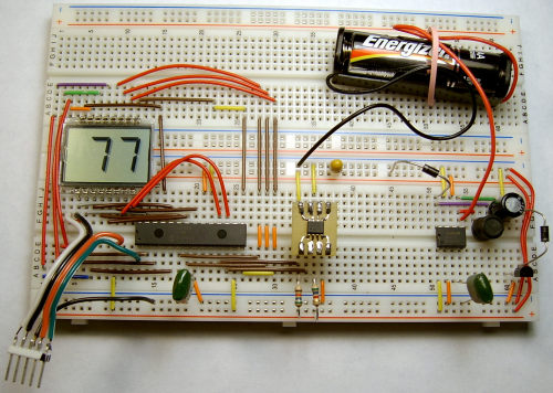
The sensor is connected to the PIC via pins RC0/VLCD1 and RC1/VLCD2. Normally, these pins are used for the LCD BIAS voltages in a non-static mode. However, it turns out that they are just normal I/O pins in the LCD static mode, which is not clear from the documentation and discovered experimentally. The 5-pin connector in the left bottom corner of the image is intended for PIC programming by using the ICSP (In-Circuit Serial Programming) mode and goes to my Brenner8 USB programmer during programming only. The components on the right part of the image around MAX756 chip belong to the DC-DC converter that delivers 5V voltage from a single 1.5V battery. The TCN75A sensor is put on a small PCB for a convenience. The two pulling-up resistors of the I2C bus are 5.6K each.
Software
The code starts with four subroutines used for LCD 7-segment codes. The pin assignment between the LCD and PIC is based on a convenient PCB layout (this part of the project is not completed yet). This lead to the situation that both LCD digits are driven from different parts of the PIC LCD Data registers, so four 7-segment codes are needed to update the LCD digit-by-digit. All variables used in the code are placed in the shared area of all banks, thus minimizing the switching between them. This way the banks are only switched to access the SFRs when it is inavoidable. A major part of the initialization is for setting up the LCD module. To save power and extend battery life the PIC is put into a sleep mode. The PIC’s watchdog timer awakes the PIC every 8 seconds (approx.) to start a new temp measurement. The PIC is driven from the internal 31kHz oscillator, which is also used for the LCD module and watchdog timer. The main loop of the code works at each PIC awake from sleep and the performed tasks alternate between sending to the sensor a request for a new temp conversion (which typically takes 250 msec) and reading the temp digital data from sensor. The thermometer is intended for an indoor usage where the temperature normally does not fluctuate very fast. The display is updated every 16 seconds which is quite appropriate.