Summary of Digital clock ds1307 using PIC microcontroller
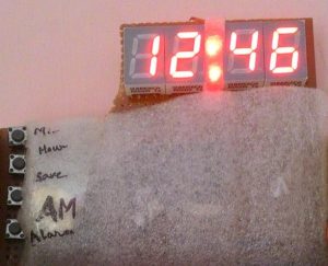
The article describes a digital clock project built using the AT89S52 microcontroller from the 8051 family. The clock uses three 7-segment displays for time display, with individual ports rather than multiplexing. A 12MHz crystal oscillator provides the timing, aided by interrupt functionality for accurate seconds counting. LEDs indicate AM/PM and alarm status, with some LEDs blinking at intervals to denote seconds. Additional components include capacitors, resistors, a piezo buzzer, and push switches. The project emphasizes basic microcontroller interfacing and timing implementation.
Parts used in the Digital Clock Project:
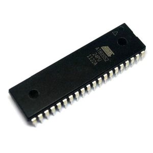
- AT89S52 Microcontroller (8051 family)
- 7 segment displays (3 units)
- 12MHz Crystal Oscillator
- Capacitors (10uF, 33pF/22pF)
- LEDs (including AM and alarm indicators)
- Resistors (330 Ohm)
- Piezo buzzer
- Push switches
Step 1: COMPONENTS REQUIRED
6 components needed :
1. Microcontroller (I have used AT89S52-8051 family), any programmable microcontroller can be used.
2.7 segment display
3.Crystal oscillator (12MHz)
4.Capacitor (10uF, 33pF/22pF)
5.LEDs
6.resistances (330 Ohm)
7.buzzer (piezo)
8.push switches
And I’m not including soldering iron, wire, flux….. electricity !!! help me out 🙂
Step 2: Circuit Diagram
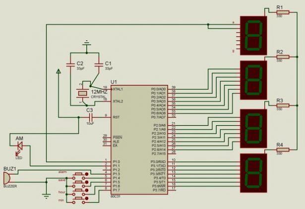
This is the circuit diagram of the digital clock using 8051 microcontroller.
As we can see the microcontroller is connected to three 7 segment display with distinct ports not multiplexed and the last hour digit is only connected to a pin as it only shows 1.
LED and buzzer are self explanatory according to the code.
1 of the LED is for AM and I have connected another LED not shown in the figure for alarm.
Crystal Oscillator of 12MHz is connected to clock speed and attaining the exact 1second counting using the interrupt property of the microcontroller.
THE MIDDLE LEDS DENOTING SECOND ARE CONNECTED TO “28TH AND 32ND” PIN.
Please pardon me, 3 LEDs aren’t shown in the circuit diagram for my laziness.
28th pin LED: first 30 second blink
32nd pin LED: rest 30 second blink
****contributing to a whole minute!!*** i’m sure after this project I came to know 60 second makes a minute!!! WOW