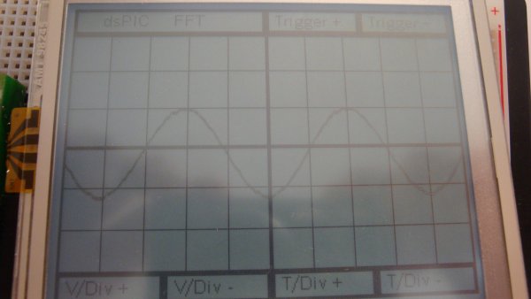
I have seen many examples of microcontroller oscilliscopes on the web and have had an itch to build one myself. In order to accomplish this my initial thought is to sample an input (ADC) at consistant time increments and then display the waveform on a graphic lcd display. If I want to change the time scale I can just change the rate of time between samples, and if I want to increase the voltage scale I can scale the measured values by some multiple.
With that basic concept, this project will require an ADC, microcontroller, graphic lcd, and some form of input. After doing a bit of search for the LCD display this link was selling a 4 inch display with touch screen for a mere $25 (which is dirt cheap for that type of resolution if you check sparkfun or other website). So now I had the display and the input source, though more thought will be needed to have graphical interface, the next item to tackle was the ADC. I had a few 24bit Microchip microcontrollers that had onboard ADC that could sample at 1.1 Msps, as they were designed to be optimized for digital signals. Not only that but they can sample multiple channels at one time which would be good for a two channel oscilliscope (if I decide to upgrade later on). The chip is a dsPIC33FJ128GP802, and it also has the capability to do sampling in the background while filling up an onboard DMA so that the only work in code will be to draw the display, plot the data, and handle inputs. The dsPIC33 is a 16 bit processor as opposed to the 8 bit processors which makes math on larger values much easier and quicker. On that same note, it also can run up to 40 MIPS so there should be plenty of speed if math operation may be needed to do an FFT or other analysis of data.
Initially in testing I was interfacing the touch screen with an onboard ADC of the microcontroller, but after thinking about how that ties up a resource I decided to go with a dedicated touch screen controller the AR1010, which is another Microchip product. I’m not trying to show a bias, I was able to get free samples of both chips (uC and Touch Controller) so they kept the budget low, and I really like the organization of datasheet put out by Microchip.
There is still one looming problem, and that is the fact that the dsPIC only works at voltage levels of 3.5 volts. This isn’t very useful if 5/12/24 volt waveforms want to be analyzed (I left out 120 because of safety issue that I don’t want to mess around with). So in order to scale down the signal I’ll need some sort of voltage divider network and an opamp to isolate and match the impedance of the dsPIC’s ADC input. Basically I would rather destroy a generic op amp before I hurt the main controller of this project. An idea I found from Texas Instrument was this, and I have ordered samples of their opamps to try and design this circuit but they don’t come in a DIP package. Another idea I found was here, which is from an AVR base oscilliscope and it just uses some generic opamps.
Read More: PIC based Oscilliscope

