Dowload the project by clicking here. The zip file contains all the following files:
- prj1.html – You’re reading it – contains the project description
- Assembler
- assemble16-win32.exe – a Windows-compiled HEX assembler to convert your assembly code to HEX for your RAM.
- assemble16-linux.c – source code for the HEX assembler for Linux and Mac users.
- README-assembler.txt – explaination of how assemble16-win32.exe works
- Standard Microcontroller – contains the files necessary for the standard portion of the project.
- fsmrom.exe – Windows-compiled version of the fsmrom
- fsmrom.c – source code for fsmrom (for Linux and Mac users)
- Makefile – Makefile for fsmrom.c
- example.fsm – An example of how you’re supposed to write your microcode.
- README-standard.txt – explaination of how the compiler for the standard microcontroller works
- Bonus Mircocontroller – contains the files necessary for the bonus portion of the project.
- example.xml – An example of how you’re supposed to write your microcode. The states in this file don’t really exist, so don’t use them.
- MICOCompiler.jar – translates your microcode into three HEX files
- MICOCompileSourceCode.zip – The source code for MICOCompiler.
- README-bonus.txt – explaination of how the compiler for the bonus microcontroller works
- Images
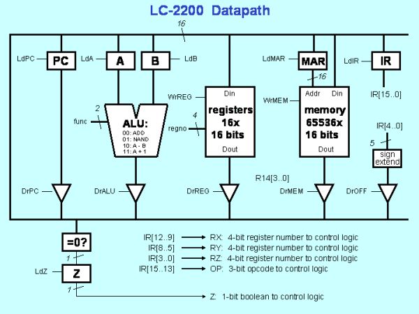
- lc2200datapath.png – image of the LC2200-16 datapath
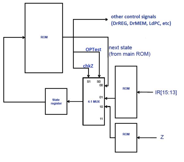
- rom_fsm_control.png – image of the standard, one ROM microcontroller
- three_rom_contoller.png – image of the bonus, three ROM microcontroller
Project Overview:
Project 1 is designed to give you a good feel for exactly how a processor works. In Phase I, you will design a datapath to implement a supplied instruction set architecture. You will use the datapath as a tool to determine the control signals needed to execute each instruction. In Phases II and III you are required to build a simple finite state machine to control your computer and actually run programs on it.
Note: You will need to have a working knowledge of GT Logisim. Make sure that you know how to make basic circuits as well as subcircuits before proceeding. Also, make sure you have the most updated version of GT Logisim! It can be found here.
The assignment is broken up into three phases:
- Phase I:
- Understand the ISA
- Design and Implement the Datapath
- Phase II:
- Design and build your Microcontrol Unit
- Phase III:
- Write the control program.
- Convert to hex (with a supplied tool)
- Hook up the state machine and run your computer.
- Test and Debug
But first you need to see the detailed specification of the Instruction Set Architecture or ISA
The LC-2200 Instruction-Set Architecture
The LC-2200-16 (Little Computer 2200-16 bits) is very simple, but it is general enough to solve complex problems. (Note: This is a 16-bit version of the ISA specification you will find in the Ramachandran & Leahy textbook for CS 2200.) This section describes the instruction set and instruction format of the LC-2200. The LC-2200-16 is a 16-register, 16-bit computer. All addresses are word-addresses.
Although, the 16 registers are known as general purpose they are generally assigned special duties by software convention.
egister 0: This register will always contain zero when read from. As an additional feature it may be written to in those cases where a value is not needed.
Note: For the purposes of this project, you must implement the zero register. Regardless of what is written to this register, it should always output zero.
Register 1: Although this is a general purpose register by convention, programmers should not use it. It may be used by the assembler when processing pseudo-instructions.
Register 2: Is designated as the register used to return values from functions.
Registers 3-5: Are designated to be used for passing arguments to functions.
Registers 6-8: Are designated for temporary variables.
Note: When calling a function the programmer should assume that the contents of registers 2-8 that were present when the call was made will no longer be valid. Thus, if needed after the call those values should be saved by the programmer calling the function.
| Reg# | Name | Use | Callee Save? |
| 0 | $zero | always zero (by hardware) | n.a. |
| 1 | $at | reserved for assembler | n.a. |
| 2 | $v0 | return value | no |
| 3 | $a0 | argument | no |
| 4 | $a1 | argument | no |
| 5 | $a2 | argument | no |
| 6 | $t0 | temporary | no |
| 7 | $t1 | temporary | no |
| 8 | $t2 | temporary | no |
| 9 | $s0 | saved register | YES |
| 10 | $s1 | saved register | YES |
| 11 | $s2 | saved register | YES |
| 12 | $k0 | reserved for OS/traps | n.a. |
| 13 | $sp | stack pointer | no |
| 14 | $fp | Frame pointer | YES |
| 15 | $ra | return address | no |
For more detail: CS2200 Intro to Systems and Networks