In this Instructable we’ll show you hot to make a GSM Access Control System for your hackerspace/garage/house/bedroom/dormroom/laboratory just like the one we built for eLab Hackerspace. We only used some scavenged parts but they can be replaced with similar parts with minor changes.
It also allows you to choose which music should be played when a certain member enters the space! 🙂
Our main idea was to make a system that would allow anyone to open the hackerspace door using any cell phone just by ringing a phone number 🙂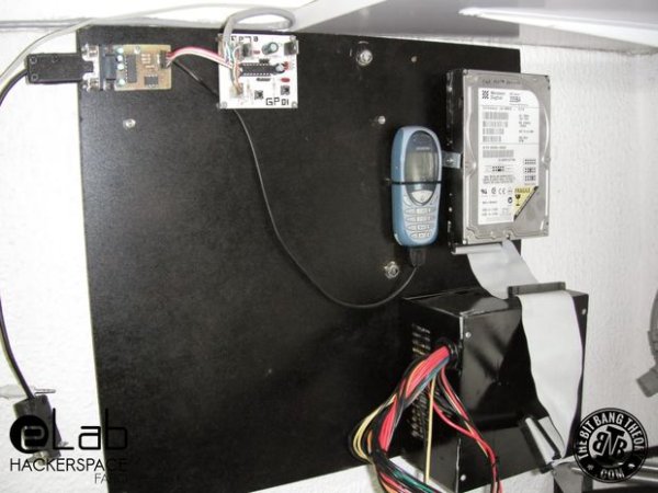
For this instructable you will need the following parts:
– Siemens C55 cell phone / GSM modem / other cell phone with support for AT commands
– Data cable for cell phone or GSM modem
– Old computer / Raspberry Pi / BeagleBone Black / other single board computer
– PIC16F88 microcontroller / Arduino / other microcontroller
– ATX power supply / other 12V/5V power supply
– cables
– connectors
– DC geared motor
– screws
– MDF board / Acrylic Board
– Solder
– Hot Glue
– Discrete electronic components (resistors, capacitors, LEDs…. )
– Audio speakers
And the following tools:
– Side cutters
– Pliers
– Screwdriver
– Soldering Iron
– Hot Glue gun
This instructable has 7 main steps:
1 – Door opening mechanism
2 – Preparing the parts to be assembled
3 – Siemens C55 working as a GSM modem
4 – RS232, TTL and LVTTL serial communications board
5 – PIC16F88 board
6 – PIC16F88 programming
7 – Python application to send data to Google spreadsheets
This instructable has all the necessary information to make a similar system. However, if you are interested in more details and seeing better quality pictures check the original post on: http://www.thebitbangtheory.com/2013/11/elab-hackerspace-gsm-access-control-system/
Step 1: Door opening mechanism
The door of eLab Hackerspace is an aluminium door with an emergency exit lever. We weren’t allowed to drill or modify the door in any way, so we tried to find a way of using the lever to open the door. We engineered a way of using a geared DC motor to pull it to open the door and also found a way of attaching the motor to the door without any drilling or glueing. We attached the motor to a piece of metal and then used the silicone frame of the aluminium door to hold it in place. It turned out to be surprisingly easy to put the motor in place. To pull the lever, we placed an off-centered pin in a gear that was attached to the motor’s axle and then used a small piece of a pulley taken from an old printer to attach the off-centered pin to the lever. It’s basically the same type of mechanism used in car pistons. In case your door does not have an opening lever, you can use any other mechanism to open it either using an electronic lock, or by using a gear motor to open the door in any other way. You just have to be creative 🙂
We also added a switch that would be triggered by the rotating gear when the lever was in the “open” position. After the mechanics of the system were done, we designed a simple board with a PIC16F88 microcontroller (more details about the board on step 5) based on the PIC16F88 prototyping board that we had previously designed for us to use at the hackerspace. We also did some simple programming of the PIC16F88 just to test the door opening mechanism: when a button was clicked, it would turn on the motor until the “open” switch was activated, then wait three seconds, and then turn on the motor again until the “open” switch stopped being activated, which meant that the lever was in the “closed” position. However, we ran into our first problem: the motor was so noisy that it was generating voltage spikes in the pin that was supposed to read the switch. We tried putting the noise filtering capacitors in the motor’s pins, tried using a more stable power supply, but we weren’t being able to filter it using hardware. After some time trying to fix the problem using hardware, we remembered a simple and clever way that worked like a charm: implement a software mechanism that would ignore isolated voltage spikes. We simply implemented a counter and defined a counting threshold: the PIC16F88 would count every time that the pin read a logic 1 but would only consider that button as being activated when the threshold value was reached, The counter would increase its value with the voltage spikes, but when the switch was actually activated, the counting value would increase extremely fast, reaching the threshold value. Having the opening/closing mechanism ready, it was time to start assembling all the control system and work on the GSM part of the system.
Step 2: Preparing the parts to be assembled
In order to keep everything organized we mounted all the parts in an MDF Board on the wall next to the door. We previously painted the MDF board black and screwed it to the wall. To make it look better, we also painted the ATX power supply black with spray paint.
Step 3: Siemens C55 working as a GSM modem
In case you didn’t know, some old cell phones such as the ones from Siemens, Nokia and Samsung are really good for electronics projects. Some of them can be used as GSM modems, having a simple serial connection and a communication protocol based on AT Commands. The amount of supported commands may vary, depending on the model of the phone and on the manufacturer. The Siemens C55 turns out to be one of the best phones for electronics projects since its GSM modem supports a wide list of AT commands.
The first thing we needed was a SIM card. Luckily we had a SIM card from Vodafone that was given to a member of eLab Hackerspace in some promotion. The card had a prepaid plan with no mandatory payments. The only obligation to keep the number active is to make a phone call every 6 months. The card also came with a bonus of 5€, which should last forever making only a 1 second phone call twice a year 🙂 The second thing I needed was a serial data cable for the Siemens C55, which we didn’t had :\ We tried to find a cheap cable on ebay but we were out of luck. However, we had two Siemens chargers with the correct connector but only with the VCC and GND pins. We had no option but to hack one of the connectors to add the Tx and Rx pins and it worked just fine! 🙂 Once we had the connector ready, we searched online to find which was the default baud rate for the Siemens C55 and found some websites saying that it was 9600bps, and others saying 38400bps. After searching for the baud rates, we connected the Tx and Rx pins to the Rx and Tx wires of a USB to Serial LVTTL cable and used putty to establish a serial connection with the phone. We decided to try with 9600 first. Once the connection was open, we typed “AT” and saw the letters being echoed to the putty terminal, which was a sign that the phone’s GSM modem was replying and using a 9600 bps baud rate 🙂 After clicking “Enter” the phone replied “OK” which, once more, was a good sign that the GSM modem was replying to the AT commands. Then we used the command “AT+CPIN=xxxx” , where <xxxx> is the pin of the SIM card, followed by “Enter” and once again the modem replied with “OK”. 🙂
When someone makes a phone call to the phone number of the card inserted in the GSM modem of the phone, it usually only replies with “RING” every time you hear the calling tone. In order to activate the identification of the calling numbers, we had to send one more command: “AT+CLIP=1”. After issuing this command and making a new phone call, the phone finally replied with:
<pre> RING
+CLIP: “911234567”,161,,,,0
</pre>
We finally had the confirmation that the phone could provide all the data that we needed to continue the development of the access control system. 🙂
By the way, if you try to send AT commands to a phone, it may happen that it won’t echo the characters that you send it. Some phones come with the echo disabled. It may happen that you type “AT” followed by “Enter” and only receive the response “OK”. To activate the echo, you can send the command “ATE1”. To deactivate it, you can send the command “ATE0”. If you wish to know more about AT commands for the Siemens C55, see this document.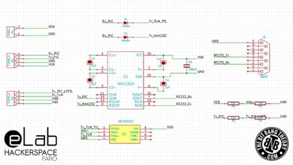
Step 4: RS232, TTL and LVTTL serial communications board
The next step was to establish a serial connection between the PIC16F88 board, the Siemens C55 Cell Phone and an old computer via RS232 connection. Once again we faced some problems: the PIC16F88 was supplied with 5V and was working with TTL levels, the Siemens C55 phone required LVTTL levels and was not tolerant to TTL (it would turn itself off), and we still had to establish a connection with the computer using RS232 levels. Moreover, we had do create a UART communication with one Master (the PIC16F88 board) and two slaves (the Siemens C55 and the computer) which is something that requires a little trick to work. This trick consists in placing a diode in the Tx line of every Slave device, with the Cathode facing the device. Why is this necessary? Well, according to the UART specifications, when a device is in the inactive state (idle), its Tx pin must be high. When communication occurs, it is the Slave’s responsibility to pull the Tx line down to sink the Master Rx channel’s current. Using the diodes, when in idle state, every Slave is able to keep his own Tx high irrespective of what the master’s Rx channel is at. A single Slave can transmit by pulling his Tx line down without affecting the Tx on other slaves. Having the Master/Slave trick done, it was time to do some level conversion. To convert the 5V TTL signal from the Tx pin of the PIC16F88 to an LVTTL level, a voltage divider using two resistors was used. To convert the 3.3V LVTTL signal from the Siemens C55 Tx pin to 5V TTL, an MCP6002 Op Amp was used as a comparator, pulling the voltage level to 5V every time the Tx signal from the cell phone passed the 2.5V threshold value, defined by a voltage divider built with two resistors. The conversion between TTL and RS232 levels was a lot simpler and was done by using a single MAX232 chip. Below you can see the PCB and the schematics where you can identify all the parts that have just been described.
For more detail: eLab Hackerspace GSM Access Control System