Xmas coming and we need some new hardware.
Xmas hardware has to be green + white + red + blinking.
So PCB is green + white, then add some blinking LEDs and we are done. I have lot of “Right Angle Side View Red Clear Ultra bright SMD 0806 LEDs” (1206 work as well) , then we have almost everything.
Step 1: Schematic
OK, we have idea. hat we need next is some schematics.
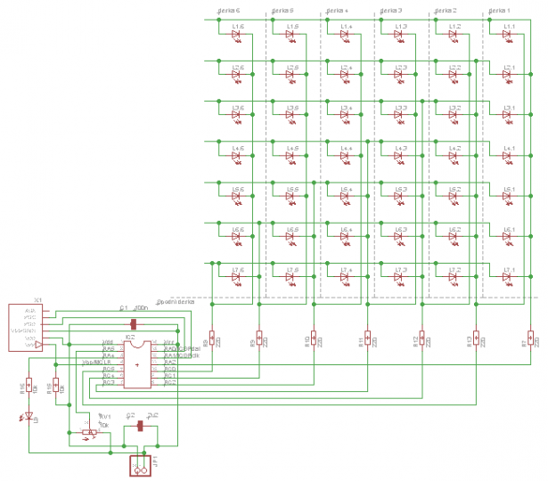
To be able to handle lot of LEDs with not so complicated device, the good idea is to use charlieplexing. Charlieplexing is close to matrix, but it combine rows and columns together. The idea is to have 6 sided tree, then with usual principles e can use charlieplexing matrix 5×6 or 6×7. Well, it is xmas, then use bigger. I decided to use matrix of 6 columns and 7 rows. Then we need MCU with at minimum 7 GPIO pins every with possibility to work as output and input (or 3rd state). One of cheapest is PIC16F15323.
We have free pins, then for example utilize A/D converter for some work and put one led on top.
OK, then schematic is on place.
Next part is decide, how to arrange board.
Attachments
Step 2: Board
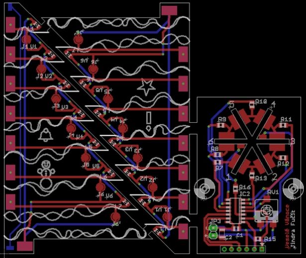
My plan is, to have generic board, that can be used 6×. One board per each column.
Lets assume, we have 2 sided board, we can have two columns per board,
one side feeding LEDs from top to down, second from down to up. We must have place, where we split those two feeds. For splitting PCB lines we have two usual options.
- We can use knife and cut cooper line (you have to be accurate, otherwise you will damage board)
- Or we can drill out cross side junction (called “via”)
I prefer drill out. It is more easy and less visible.
We also need to feed rows, but we have to select proper one that is feed from respective column. I decided to use PCB soldering junction. That is easy and almost free of charge. Then on every board, that represent one column we have one “junction” Jx and one “via” Vx that represent particular board x. It mean, that on board 1 we have to solder “junction” J1 and drill out “via” V1. One small excuse is board 6, that have to feed two rows and then have two “junctions” J6 and J6′.
Last part is to create “base” board, that will contain MCU and rest of electronic components. This board is relatively simple with no special functions.
Attachments
Step 3: PCB Order
I use china manufacturing for board ordering.
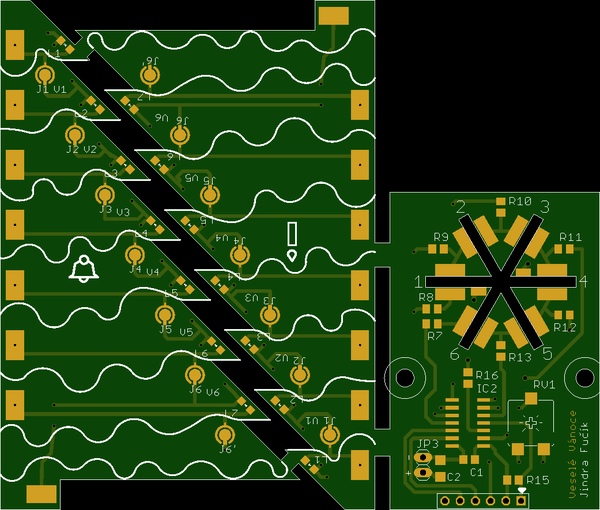
One of faster and comfortable for me is AllPCB. They have simple ordering system. On first page enter dimension. For this board dimension is 85 × 100 mm, select quantity (do not forget, that you need 3 pcs per one tree), keep 2 layers and keep 1,6 mm thickness. Click quote now and then you will get price including shipment.
You can adjust board colors, but green is the best color for tree and white is the best one for snow imitation.
Enter your email address and click “Add to cart”.
You will be asked for “gerber file”. That is attached charlieplex7_85x100_brd.zip file, then upload it. Chose your address, preferred payment method and finish order.
Attachments
Step 4: Prepare PCB and Parts Solder
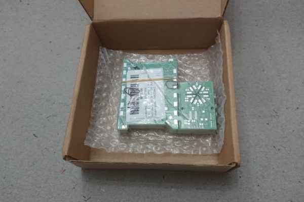
Within few days you can expect package with PCBs.
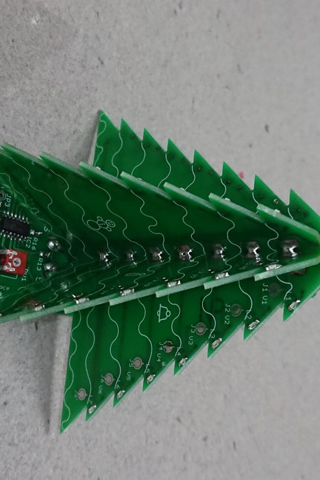
First of all we must split boards. They are connected using small bridges. For easier ordering here is connected three parts together. I’m using shears, that is fast, but using JLC razor saw make cut more smooth.
When cut is complete, prepare which board will be used for which column. Be careful, when selecting boards for columns 3 and 6. Boards 3 and 6 must contain on back side extra wire for top mounted LED. Boards with this extra wire are that one with snowman and bell images.
Next step is drill out respective vias and solder junctions.
Then solder all SMD LEDs, processor resistors and other electronic parts to six column boards and one base board.
Step 5: Solder Together
When all SMD electronic parts are soldered, it is time, to solder boards together.
First step is solder all six column boards to base board. Start with small points on one side (for example top side only). solder boards. Solder boards carefully, focus to put boards close to center but that close, to create hexagon in middle.
When all six boards are attached to base board, use one spare empty base board as holder. Draw this spare board on top of column boards, it will fix column boards in expected position and distance. It make all construction more stable and it is more easy to solder about three bottom rows on boards. When done, solder back sides of boards, re solder top sides to final state and do not forget those two extra wires for top LED.
After that remove helping spare board and finish soldering of all columns.
Last step is THT top mounted LED. Cut out wires of this LED, format led to fit to back of boards and solder it to the position with cathode on board 3 and anode on board 6.
That is all from soldering point of view.
Step 6: Software
Software is very easy.
I prepared simple example, that using tables traditional for Microchip PIC MCUs. The software use one timer for interrupt to walk through LEDs and display frames stored in “video” RAM.
Main program only watch for next step. Shift data in “video” RAM and put next column to it.
It also read value from DA converter and use it for duration of next frame.
You can download source code and modify it, or you can download hex file only and use it as it is.
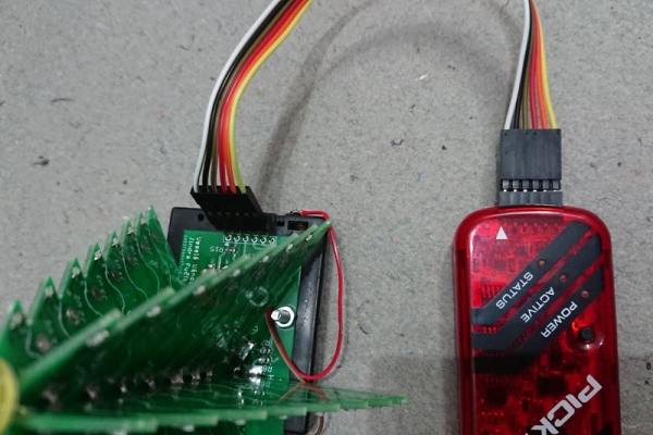
I’m using PICkit3 for programming of HEX to processor.
HEX file is programmed to finished xmas tree using six hole 0.1″ socket X1. It is no necessary solder any connector here. Use direct wires delivered with PICkit 3 with pins on both sides. Pass pins through holes and gently press them in holes.
Board contain same triangle mark for pin 1 as PICkit3. When programming, check, that wire marked by triangle on one PICkit3 is in marked hole in board.
I’m using MPLAB IPE (Integrated Programming Environment) for programming.
Before programming start, do not forget to enable powering of board from tools. That option is available on “Power” tab of IPE.
After programming, tools will keep board powered, then you can directly check the result.
Attachments
Step 7: Finalization
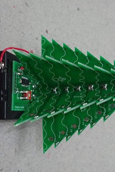
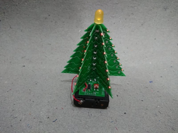
Final part is mount battery pack as stand.
I’m using 3× AA battery holder. This holder usually have two holes for two M3 screws. Base board have same holes, then mounting is easy by using two M3×12 screws and respective nuts.
Before mounting, solder power wires to base board and to battery holder.
And that is all. Plug three battery and enjoy.
Source: Charlieplexing Xmas Tree