For a recent project, I needed to boost the output from a USB (high ampage charging) port from 5V up to 18V to power an amplified speaker. I decided to try rolling my own boost converter (mainly because playing with big inductors sounded cool). My first attempt was a dismal failure (it could only source about 10mA and I needed 600mA!) but, after reading TI’s guide to calculating components, I managed to get it working pretty well. (I also converted the calculations in that guide into a spreadsheet to make it easier to work through it.)
It turns out that component selection is a reasonably big deal for a converter or this type. Even after you’ve got the right “headline” value for a component, there are other factors you need to worry about too…
Step 1: Basic Principle
Wikipedia has a good explanation of the principle but here’s a quick guide:
- The boost converter rapidly switches a switch on and off. (My design runs at 65kHz.)
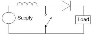
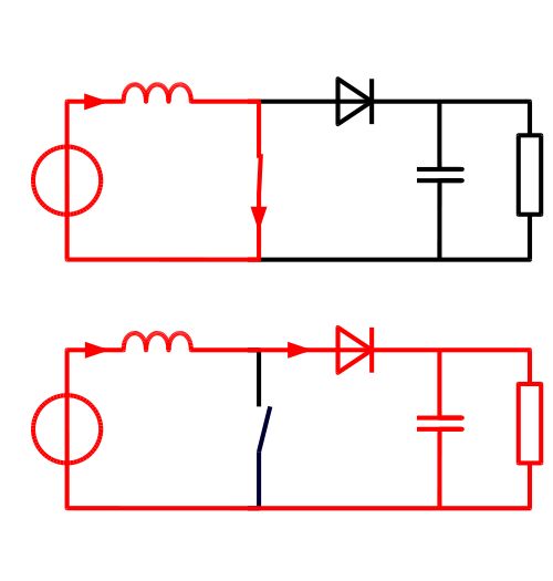
- When the switch is closed (first diagram), it connects an inductor across the input supply while the diode blocks any current from flowing back from the output side.
- The inductor charges up. (Although it seems like shorting a coiled piece of wire across the input should waste a lot of power, the inductor actually stores up the energy in its core.)
- When the switch opens, the inductor resists any change in current (and, shorting it across the supply means it has a lot of current going through it). Since the output side has a much higher resistance than the switch, the inductor has to raise its voltage to keep the current flowing. (Resisting change in current by changing their voltage is the magical property of inductors.)
- The output capacitor charges up from the inductor plus the power supply at the higher voltage.
- When the switch turns on again, the capacitor is charged at the higher voltage and powers the load until the next cycle. Since power is only ever applied to the output side part of the time, there will always be a ripple on the output voltage.
- If the switch is on for a relatively longer time in each cycle (it’s duty cycle is higher) then the inductor stores up more energy, resulting in a higher output voltage when the switch turns off. Controlling the duty cycle lets you adjust the voltage.
So much for the principle, how do you turn that into a real circuit?
Step 2: Choosing the Key Components
For exact values, I’ve put together a template Google spreadsheet that does the calculations from the TI guide. Below, I’ve tried to sum up the rules of thumb that I gleaned after reading that document and searching around.
Inductor
The inductor is the most important part of the circuit.
- It’s headline value is its inductance, measured in Henrys. The spreadsheet will help you calculate the right value. I recommend going for 1.5-2x the calculated value so you have some headroom.
- You also need to check out:
- The current rating, this needs to be enough to handle the peak current in the inductor (as calculated by the spreadsheet).
- Shape: I went for a toroid because they’re supposed to have low EMF interference. One source that I read said that bobbin inductors were the best bang for buck if you weren’t worried about interference.
- The core material, you want one that’s suitable for a power inductor. I went for a toroid that was marketed as a power inductor. I believe it has a ferrite core.
I used this 150uH inductor.
Switch
This is the second most important piece of the circuit, and where I made a mistake first time around. A MOSFET is a good choice because it’s easy to drive with a microcontroller. You need to look out for:
- Rds(on) This is crucial, it’s the resistance of the switch when it’s turned on. My first attempt was scuppered by having a too-high value here. <10mOhm is ideal. If this is too high then the inductor won’t be able to draw enough current and you’ll waste power in the switch.
- The Vgs(th) value, this is the voltage you have to apply to the gate of the transistor to turn it on. If you’re using a 5V microcontroller, this needs to be 1-2V.
- Vds(max), this is the maximum voltage the transistor can handle, go for the output voltage plus some safety margin.
- Ids(max), the maximum current that the switch can handle. This needs to be bigger than the peak current according to the spreadsheet.
I used this switch.
Capacitors
The spreadsheet should calculate the minimum values for the capacitors in the circuit. I found that, powering an audio amp, I needed a much bigger output cap than was specified.
- The capacitors in the output stage need to have a low ESR value for efficiency.
I chose a large, electrolytic capacitor with low ESR and then put in parallel with a 22uF ceramic capacitor in the hope of filtering the output further.
On the input side, I used the same setup.
Diode
The diode is fairly easy, just go for a Schottky diode that can handle the average current and has a low forward voltage (450mV seems to be the limit for non-exotic parts).
Microcontroller
I went for an ATTiny84A because it’s available in through-hole packaging, it’s not too big and the AVR GCC toolchain is pretty good. I followed this tutorial from Lady Ada to get the toolchain up and running and I used AVR Eclipse to develop the code. I needed fairly precise control of the hardware to get the PWM running at 65kHz so it might have been difficult with the more-abstract Arduino IDE.
Source: Boost converter using IR2110 and pic microcontroller