When I designed the “YAP” for the “YAP” PICMicro programmer presented in “Programming and Customizing the PIC Microcontroller”, I felt that the serial interface provided in “execution mode” of the programmer would be very useful for people developing their own software. With this interface, the user could input new values into the PICMicro application or output temporary values to help with debugging. This feature was probably not considered that useful until I developed the “YAP Windows” interface software with a Terminal Emulator built into it for just this purpose. This Terminal Emulator interface is shown in the screen shot above.
In this article, I want to focus on how asynchronous Non Return to Zero (“NRZ”) serial interface software is written for the low-end and mid-range PICMicros which do not have built in UARTs. There are many sources for information on creating the electrical side for this interface (and the YAP provides this as a matter of course), so I really haven’t persued it in this article.
If you are looking for more information on the electrical side of things, check out the Maxim “MAX232” chip at http://www.maxim-ic.com (seach under “Interface Products”). The MAX232 is commonly used for this purpose because it only uses a single +5 Volt power supply, is widely available and has been second source (which means it is very cheap). When I design RS-232 interfaces, I normally create a “Three-wire” (TX, RX and Ground) interface and short CTS-RTS and DSR-DTR together to avoid having to worry about hardware “handshaking” in my applications.
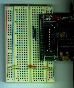
Because the genesis for this topic was the “YAP”, I used a YAP as the only hardware for the application. As can be seen in the picture below, Pin 5 of the YAP’s debug connector (Serial Input) is connected to Pin 10 (the PICMicro’s RA3) and Pin 6 (Serial Output) is connected to Pin 11 (the PICMicro’s RA4 Pin).
The pins that were chosen are arbitrary, with RA4 being selected as an input simply because most applications do not require the “open-drain” capabilities of the pin. The serial signals used in the application are at TTL/CMOS levels with the YAP providing the electrical level conversion, eliminating the need for level conversion circuits to wire the PIC16F84 to the YAP’s serial I/O.
The macros presented in this article are designed to use any of the PICMicro’s I/O pins. If RA4 is used for serial output, make sure a 1K to 10K pullup is put on the line to allow it to be used to output digital signals.
Before going through the code for the article, I just want to review what I mean when I say “asynchronous Non-Return to Zero” serial communications. This method of communication has been around for many years; first used as part of the “Baudot” standard for teletypes. In modern communications, each byte is transferred in “8-N-1” format which means that eight data bits are sent with a single (“low”) “Start Bit” and High “Stop Bit” to make up a data “packet”. This is shown in the diagram below:
For more detail: Bit-Banging Serial Interfaces for the Low-End and Mid-Range PICMicros using PIC16F84