
Summary of How Seven Segment Display Multiplexing with PIC Microcontroller for Electronic Sign
This article explains interfacing multiple 7-segment displays with a PIC microcontroller using multiplexing to save pins. By rapidly switching between units based on the "persistence of vision" principle (over 25 frames per second), all displays appear active simultaneously. The method involves connecting all segment lines to one port and enabling individual display units sequentially to show different numbers like 1, 2, and 3.
Parts used in the Seven Segment Display Multiplexing Project:
- PIC Microcontroller
- Seven Segment Display Units
- Display Driver ICs
- Common Cathode Pin
- Segment Pins (A, B, C, D, E, F, G)
- PORT B of PIC Microcontroller
Hi there, today I’m gonna to give you some PIC interfacing circuit. We have already seen how to connect LCD display to PIC MCU which has a great role in electronic display board industry. By the way how do we interface 7 segment displays to PIC microcontroller? Some of you guys may already familiar with seven segment electronic displays and their interface with display driver ICs. For a single 7 segment unit the, process is quite simple, since there are 7+1=8 pins in a display unit. So how to connect 4 or 5 units together?, which is very common in digital display systems. Since we have limited pins (only 40) available in a PIC microcontroller.
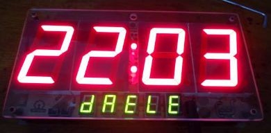 To overcome this situation we use a technique called Seven Segment Display Multiplexing based on the theory of ‘Persistence of Vision’ of our eyes. Human eye can’t notice that visual change if rate is 25 (or more) frames per second. Each display is turned ON for this period by continuous switching and our eyes will consider that the display is turned ON constantly.
In this way we are using simply 7+1 pins (A, B, C, D, E, F, G → Segments and DP → Period or Dot) to interface all of the display units.
Now let’s see logic behind seven segment display multiplexing in digital display boards.
- There will be one ENABLE pin at each 7 segment digital display unit (it specifies common anode or common cathode). Time being we consider common cathode display (when the common pin receive LOW (0V) the unit will be active). Our aim to write 1 2 3 numbers on 3 display units respectively. The procedures are followed.
- All the A, B, C, D, E, F, G, DP pins of 3 units are shorted each other and connected to the PORT B of PIC Microcontroller. (In my example I just skipped DP)
- Send data 1 (0x06) to the shorted lines and enable 1st unit.
- Send data 2 (0x5B) to the shorted line and enable 2nd unit.
- Send data 3 (0x4F) to the shorted line and enable 3rd unit.
- These processes will be very fast more than 25 times per second. Hence our eye consider the unit displaying 1 2 3 all time. This is Multiplexed 7 segment display.
Seven Segment Multiplexing Circuit Diagram
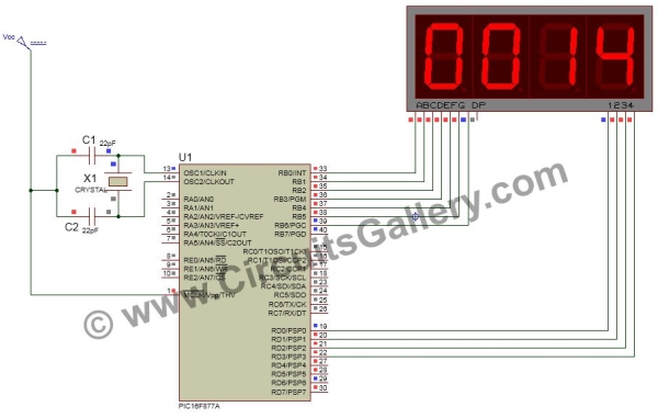
Circuit schematics for interfacing Seven Segment Display to PIC microcontroller is given below. In the following circuit I have used 4 Digit single display and it will be more easier.
For more detail: How Seven Segment Display Multiplexing with PIC Microcontroller for Electronic Sign
- How do we interface 7 segment displays to PIC microcontroller?
We use a technique called Seven Segment Display Multiplexing based on the theory of Persistence of Vision. - What is the purpose of Seven Segment Display Multiplexing?
It allows us to use simply 7+1 pins to interface all display units despite having limited pins available in a PIC microcontroller. - How does the human eye perceive the multiplexed display?
The human eye cannot notice visual changes if the rate is 25 or more frames per second, making it seem constantly ON. - Which type of display unit is considered in the example logic?
The example considers a common cathode display where the unit becomes active when the common pin receives LOW voltage. - How are the segment pins connected in the circuit?
All A, B, C, D, E, F, G, DP pins of the units are shorted together and connected to the PORT B of the PIC Microcontroller. - What data values are sent to display numbers 1, 2, and 3?
Data 1 is 0x06, Data 2 is 0x5B, and Data 3 is 0x4F. - Why is the process repeated more than 25 times per second?
This speed ensures our eyes consider the unit displaying numbers all the time due to persistence of vision. - Can this technique be used for 4 or 5 display units?
Yes, this technique is very common in digital display systems for 4 or 5 units.
