One very common thing in electronics is the need for two intelligent devices to communicate with each other. When you first see a PIC and Arduino you might think that they are two differeny systems and don’t share much in common, but you’d be wrong! In fact, the AVR and the PIC microcontrollers have many of the same types of hardware modules and some of them follow the exact same protocols for communication.
In this article, we will use a PIC 18LF4520 and an Arduino UNO to build a transmitter and receiver using some wireless modules. The PIC will output serial commands as a transmitter that tell the Arduino system to pause an LCD screen from updating a counter value. This project is intentionally designed to be simple because there are many simple ideas at play and it’s important for you to understand each one.
Purpose & Overview Of This Project
The goal of this article is to explain, design and build a serial communication transmitter and receiver. The transmitter will always transmit a specific ‘idle’ command until a button is pressed, which will tell the transmitter to transmit an ‘active’ command to the receiver. The Receiver will have a 16×2 LCD display connected to it and if the ‘idle’ command is detected, the display will be updated with a time count value. However, if the ‘active’ command is received, the Receiver system will stop updating the LCD screen to signify a pause.
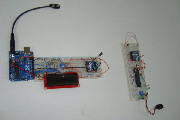
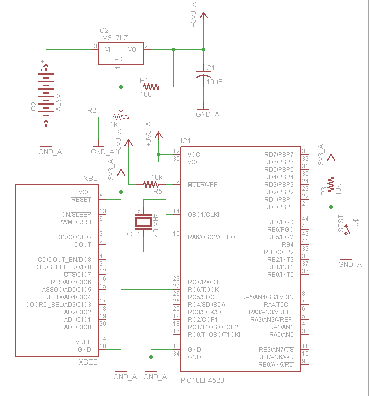
To build this system we will use XBee wireless modules which will transfer 9600 baud serial communication from transmitter to receiver. The transmitter will use a PIC 18LF4520, a 40 MHz crystal and a simple SPST button. The receiver will be a standard Arduino UNO with a 16×2 LCD Display connected to its digital I/O ports. Both of these designs will be built on a standard sized breadboards.
PIC 18LF4520
Arduino UNO
[2] XBee Modules
40 MHz Crystal
16×2 LCD Display
SPST Button
1x 10uF Capacitors
Green LED
8x 100Ω Resistor
1kΩ Trimpot
10kΩ Resistor
[2] Breadboards
Jumper Wire
+9v Battery Connector
Parts List Details
There’s quite a few parts for this project and so we’ve gone ahead and listed out the more important ones with details below.
PIC 18LF4520
This PIC microcontroller will be used to make the transmitter portion of this circuit. The hardware serial module in the PIC will be used to output to the wireless XBee module.
Ardino UNO
The Arduino UNO system will be used as the receiver for this project. The hardware module inside of the AVR on the Arduino will receive and interpret serial commands received through the XBee wireless interface.
XBee Wireless Modules
XBee wireless modules use a known protocol to transfer information wirelessly. The information is packeted which means that the modules operate with a very low loss or error rate. Gotta love these little things!
16×2 LCD Display
To provide a less boring output on the receiver’s end, we’ll use a 16×2 LCD display to let the user know when the transmitter has sent an ‘idle’ vs. ‘active’ command. 16×2 LCDs interface very easily to Arduinos so it shouldn’t be a problem!
Breadboard and Jumper Wire
We’ll use breadboards for building the circuits since everything is low frequency. Standard jumper wire will be used to connect the circuits together.
Serial Communication Signals
Each microcontroller, the PIC and the AVR (Arduino’s micro) has a dedicated serial module in hardware. It’s mostly just a super fancy digital shift register. If you look below you can see where to find the Tx (output) and Rx (input) pins on each of these devices. One common problem with connecting serial devices together is that people wire the Tx pin to Tx and Rx to Rx. Don’t do that!..instead: always remember that Tx connects to Rx and Rx connects to Tx. This will save you a considerable amount of headaches.
Understanding the theory of RS232 serial communication, means looking down deep into the actual signals being transmitted. I hooked up an oscilloscope to capture two characters being transmitted, 1 and 5. A standard single transmission of RS232 serial communication will contain a start bit, 8 bits of information and a stop bit. Since there’s only 8 bits of information, a system was invented called ASCII which is short for ~> The American Standard Code for Information Interchange.
For more detail: Arduino to PIC Communication using PIC18LF4520