Summary of Arduino solar charge controller + output control and data logging online with Xbee WiFi
The article describes a DIY solar charge controller project using an ATMega328P microcontroller and a 1.8" TFT display. It supports automatic battery type detection, data display, and IoT monitoring via Xbee WiFi with data uploaded to Thingspeak. The controller manages 6V/12V batteries (24V with modification), supports up to 10A charging and 20A output currents, and includes safeguards like load disconnection to prevent over-discharge. The project details component lists, wiring, programming with Arduino IDE, sensor connections, and internet setup for remote monitoring.
Parts used in the Solar Charge Controller Project:
- Prototyping board
- ATMega328P (28-pin through hole)
- 16MHz oscillator
- 22pF capacitors (2x)
- 1000uF 100V electrolytic capacitor
- 220uF 16V electrolytic capacitor
- 100nF capacitor
- 10nF capacitor
- 1uF ceramic capacitors (5x)
- 82 Ohm resistor
- 100 Ohm 1% resistors (6x)
- 1 kOhm resistors (4x)
- 2.2 kOhm resistors (4x)
- 10 kOhm resistors (4x)
- 5 mOhm resistors 3W minimum (2x)
- IN4007 diodes (2x)
- Power diode MBR1045
- STB80PF55 P-channel MOSFETs (2x)
- 2N2222 NPN transistors (2x)
- Reset push button
- LM35 temperature sensor
- LDR light sensor
- 25 kOhm 10-turn potentiometers (2x)
- 100 kOhm 10-turn potentiometers (2x)
- 20 Amp 2-pin screw terminals (3x)
- 20 Amp 6-pin screw terminals (1x)
- LT6105 current sense amplifiers (2x)
- MSOP to DIP 8-pin adapters (2x)
- 7-pin male header
- 6-pin male headers (2x)
- 4-pin male header
- 3-pin male header
- 2-pin male header
- 7805 (TO220 package) 5V regulator
- Xbee WiFi + shield or interface (e.g., Sparkfun shield)
- 1.8" TFT screen from Saintsmart
- Panel push-buttons (2x)
- Panel ON-OFF selector switch
- Heatsinks for MOSFETs, diode, and 7805 regulator
A while back I started working on a solar charge controller, it was based on a PIC microcontroller, a 20×4 characters display and the code was written in Assembly language. It did work well and was still working when I decided I wanted to add more to this controller.
My new controller uses a standalone ATMega328P, and a 1.8″ tft screen from Saintsmart. I wrote the code with the arduino IDE and uploaded ( many many times 😉 ) straight onto the board with the standalone uP. I had a lot of solar cells at home so I decided to build my own solar panel to go with it. Not sure of the achieved wattage, it is not so great but it still gives 23 to 24 volts when it is not connected.
This new controller has a button that allows you to turn ON or OFF an output, where the voltage from the battery is applied and where you can connect anything like LED lights, power inverter or any other devices. Maximum output is 20 Amps for this design.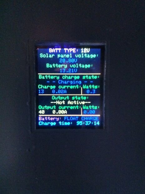
The features of this new controller are:
– Possibility to charge 6V, or 12V types batteries. (24V included in software but needs a small modification on the electronic side)
– Automatic detection of the type of battery connected.
– Push button to turn ON and OFF the output stage of the controller.
– Push button to display different information on the screen like total charge time, number of charging days, min and max battery voltages recorder, temperature, LUX values outside, maximum charging current and Watts as well as maximum output currents and Watts.
– All these values are saved to the EEPROM once a day when the ambient light goes down and are reloaded at start up.
– Possibility to erase the EEPROM and start with fresh readings, as well as possibility to delete the total charging time and days.
– The temperature of the battery is used in the software to reduce the charging values if it goes above 25° or raise them if it is lower than 25°.
– Information is sent to the IoT (Internet of Things) once every 5 minutes to be able to keep an eye on how things are going when I am not at home. Check out my channel to see what it looks like and what information is sent over by the controller. https://thingspeak.com/channels/17599
– Automatic disconnection of the load connected to protect the battery and prevent over-discharging.
– Bulk charge, followed by 1h of constant voltage charge followed by float charge.
– Maximum charging current supported by the controller is 10 Amps, maximum output current is 20 Amps.
– Maximum solar voltage input is 30V in this configuration.(limited by the 7805 maximum input voltage)
– Current consumption while on standby and not charging the battery is <10 mA.
Step 1: Build one yourself, what you need
If you wish to build one of these controller yourself then here is the list of material and all the steps needed.
I wont show the build of the solar panel here as this instructable focuses on the solar charge controller.
I have kept the fuses off the board, this is why nothing will appear on this list. I have a 10Amp fuse on the solar panel wires and a 25Amps fuse on the output wires.
Material needed:
1x prototyping board
1x ATMega328P (28pins through hole)
1x 16MHz oscillator
2x 22pF capacitors
1x 1000uF 100V electrolitic capacitor
1x 220uF 16V electrolitic capacitor
1x 100nF capacitor
1x 10nF capacitor
5x 1uF ceramic capacitor
1x 82 Ohm resistor
6x 100 Ohm 1% resistors
4x 1 kOhm resistors
4x 2.2 kOhm resistors
4x 10 kOhm resistors
2x 5 mOhm resistors (3W minimum)
2x IN4007 diodes
1x Power diode MBR1045
2x STB80PF55 P-chanel MOSFETS
2x 2N2222 NPN transistors
1x reset push button
1x LM35 temperature sensor
1x LDR light sensor
2x 25 kOhm 10 turns potentiometers
2x 100 kOhm 10 turns potentiometers
3x 2pins 20Amps screw terminals
1x 6pins 20Amps screw terminals
2x LT6105 current sense amplifiers
2x adapters for MSOP to DIP packages (8pins)
1x 7pins male headers
2x 6pins male headers
1x 4pins male headers
1x 3pins male headers
1x 2pins male headers
1x 7805 (TO220 package) 5V regulator
1x Xbee Wifi + shield or interface ( I used the shield from Sparkfun as I had one handy)
1x 1.8″ tft screen from Saintsmart
2x panel push-buttons
1x panel ON – OFF selector switch
heatsinks for the MOSFETS diode and the 7805 (it tends to get warmish at times)
And of course the usual soldering iron, hookup wires, drill and drill bits to cut tracks and make mounting holes.
Step 2: Soldering the main board + sketch and libraries
Start by soldering the main board. There is a picture of the way I wired my prototype board to help.
I made the drawing using Black Board software. You can use it as a guide or just make up your own layout.
There is also the schematics of the controller attached, to refer to for resistors values etc if needed.
Once done, you can download the sketch I made up for the controller and there is a few libraries that you might not already have installed that you ll need to install.
They are:
Adafruit_GFX.h ; download here if needed https://github.com/adafruit/Adafruit-GFX-Library
Adafruit_ST7735.h ; download here if needed https://github.com/adafruit/Adafruit-ST7735-Librar…
EEPROMex.h ; download here if needed http://thijs.elenbaas.net/downloads/?did=6
Step 3: Thingspeak website and setting up the Xbee
The data collected by the charge controller is pushed onto a website called Thingspeak. This is where I can log in and check on my charge controller when I am not at home. You can access it here to create an account and setup your own channel. https://thingspeak.com/users/sign_up. If you don’t want this feature on your charge controller you can just comment out the xbee() in the main loop section of the program and it will not take care of this while running.
If you do want to be able to check on your controller on the internet then you will have to create your own channel. Once you have created it, you will be given an API key. This key is important and will be needed in the arduino code so keep it handy. You can then setup the channel, There is 8 fields of data that are sent from the charge controller, so in your channel under the “channel settings” tab, enter the information as follow for the fields.
field 1 — solar voltage
field 2 — battery voltage
field 3 — charge current
field 4 — charge PWM
field 5 — output current
field 6 — battery charged
field 7 — temperature
field 8 — luminosity
My code for the charge controller does not create a connection for the Xbee every time it needs to send data. I have already programmed my Xbee with my personal WiFi settings using the X-CTU software.
There are some good tutorials on the internet on how to connect your Xbee and communicate with it using X-CTU. This one is very good and will get you on your way. https://learn.sparkfun.com/tutorials/xbee-wifi-ho…
Follow the tutorial to get the Xbee connected to your personal WiFi network.
Once done there is a few parameters that we will change into the Xbee to get it setup to connect onto the Thingspeak website as this is where all the data will be sent.
Change or check the following settings:
– IP protocol needs to be set to “1-TCP”
– DL- destination IP address needs to be set to “184.106.153.149”
– DE- destination port needs to be set to “50”
Once these settings have been changed, press the “write” button to store these settings into your Xbee.
You have now successfully setup your Xbee to push data onto your channel at Thingspeak.
Next, open the “Solar_charge_controller” sketch and look for line n° 1150
The line should be: xb.print(F(“key=YOUR_API_KEY_HERE”));
Delete the parts which says YOUR_API_KEY_HERE and replace it with your own personal API key that you received when you created your channel on Thingspeak. Make sure you don’t delete key= because it will not work without it.
Step 4: Powering up and loading the code
Once the board is all done, it is time to power it up and load the code into the micro-controller. I forgot to add that this ATMega328P was already bootloaded so all I need to do is load up the program onto it.
There is some pretty good tutorials out on the internet on how to setup and program a standalone ATMega if someone needs more information.
- – In the case of this board, first thing you need to do is to load the Arduino ISP example sketch onto your arduino board.
2. – In the second picture I commented to show which header is used for programming and which pins is pin number 1.
3. – Wire your arduino to your board this way.
Arduino pin 10 — board header pin 5
Arduino pin 11 — board header pin 1
Arduino pin 12 — board header pin 2
Arduino pin 13 — board header pin 3
Arduino +5V — board header pin 4
Arduino GND — board header pin 6
4. – Open the “solar_charge_controller” sketch, make sure the type of board is set to Arduino UNO and select “Arduino as ISP” in the programmer section in the “tools” menu of your arduino IDE. Try to compile the sketch (ctrl + r) to make sure it doesn’t return any error.
5. – Once it is all looking good, press and hold the SHIFT button on your keyboard and click onto the upload button arrow in your arduino IDE and if everything is working fine, you should see the little Rx Tx lights on your arduino board start to blink. (It takes a fair bit of time for the sketch to upload).
Once done you can remove the programming wires from the header.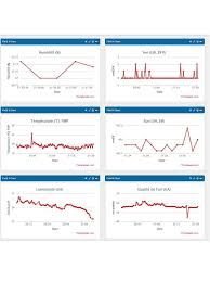
Step 5: Connecting the different sensors and cables to the board
After mounting the board in its final place we need to connect the screen, Xbee, switches and sensors to it.
On the picture of the prototype board I have commented on what header is for what device and where to find pin 1.
You can also refer to the schematics to find the headers pin numbers.
Connection for the Xbee: (from the board to the Xbee shield)
Header pin 1 goes to Shield pin 3
Header pin 2 goes to Shield pin 2
Header pin 3 goes to shield pin +5V
Header pin 4 goes to shield pin GND
Connection for the tft screen: (from the board to the tft screen)
Header pin 1 goes to screen pin Vcc
Header pin 2 goes to screen pin GND (the screen works as well when it is not connected, saves a bit of power)
Header pin 3 goes to screen pin RES
Header pin 4 goes to screen pin RS/DC
Header pin 5 goes to screen pin CS
Header pin 6 goes to screen pin SDA
Header pin 7 goes to screen pin SCL
Connection for the buttons and switch: (from the board to the buttons and switch)
Header pin 1 goes to ON – OFF switch on 1 side
Header pin 2 goes to ON – OFF switch on the other side
– From this pin of the ON _ OFF switch run a wire to the + of the OUTPUT button light
Header pin 3 goes to the GND of the OUTPUT button light (not connected in my setup)
Header pin 4 goes to the DATA button on 1 side
– From this pin of the DATA button run a wire to the 1st side of the OUTPUT button
Header pin 5 goes to the DATA button on the other side
Header pin 6 goes to the OUTPUT button on the other side
Connection for the LM35 temperature sensor: (from the board to the sensor)
Header pin 1 goes to the LM35 pin +
Header pin 2 goes to the LM35 pin GND
Header pin 3 goes to the LM35 pin Vout
For the LDR sensor, it doesnt matter which way you connect the sensor to the header so just connect it the way you want.
For more detail: Arduino solar charge controller + output control and data logging online with Xbee WiFi