Summary of 4 Channel DMX512 Driver for PIC16F688
This project is a 4-channel DMX512 driver board using four low-side N-channel power MOSFETs capable of driving up to 3A per channel. It supports 8-bit PWM mode at 100 Hz or static on/off mode to control LED arrays, low voltage lamps, or relays. The configuration is stored in EEPROM, avoiding external switches. The board operates on 9-24V, with flexible DMX addressing and active-high/low output options. It uses through-hole components and excludes DMX connectors for versatility. The design emphasizes ease of construction and minimal external hardware.
Parts used in the 4 Channel DMX512 Driver Board:
- Resistors: 120Ω 0.25W (R3,8,9,10,11)
- Resistors: 10kΩ 0.25W (R4,5,6,7,12,13)
- Resistor: 330Ω 0.25W (R14)
- Ceramic Capacitors: 100nF X7R (C2,3,6)
- Electrolytic Capacitors: 10µF 35V, 47µF 25V (C4, C5)
- Signal Diode: 1N4148 (D1)
- Rectifier Diodes: 1N4001A (D2,3,4,5) [for relay/inductive loads]
- MOSFETs: STP36NF06L Logic Level N-channel (Q1,2,3,4)
- Microcontroller: Pre-programmed PIC16F688 (IC1)
- Voltage Regulator: DA78L05 5V 100mA (IC2)
- RS485 Transceiver: ST485CN (IC3)
- Header Plugs and Sockets: 2+2 way double row, 3-way single row, 5-way right angle (JP1, CON1, CON2, JP2)
- IC Sockets: 8-pin and 14-pin DIL sockets
- Terminal Blocks: 2-way 16A Interlocking Terminal Blocks (X1,2,3,4,5)
- Optional DMX Address Board Components: 1kΩ resistors, 100nF capacitors, 1N4148 diodes, 4017B decade counter, DIP switch, 16-pin DIL socket
Description
This project is a 4 channel DMX512 driver board. It features four power MOSFETs that can be configured to operate in PWM mode or as on/off outputs. The driver can be configured to use any four consecutive addresses across the full 512 channel address range. It can be used to drive LED arrays or low voltage lamps in PWM mode or operate relays in static mode.
Feature list:
4 channels with low side N channel MOSFETs providing up to 3 amps per channel
Two modes of operation:
8 bit resolution PWM mode with a PWM period of 10ms (100Hz).
static drive mode with on/off outputs.
When no DMX data is received the driver can be configured to turn off all outputs, or leave them in their current state.
Configuration held in EEPROM so no external switches or jumpers required.
Flexible modes available to set configuration.
Configurable for active-high or active-low outputs to allow ease of interfacing to external drive electronics.
One of the design goals for this project was to keep the external hardware required to a minimum. For this reason, most of the configuration is held in the PICs EEPROM. The only two hardware enabled options are Output active drive level and Config mode enable. The other goal was to make it easy to construct, to that end the PCB is single sided and uses easy to obtain through-hole parts. I also didn’t include the DMX connectors on the PCB since there are three types in use.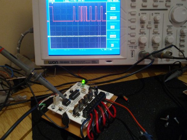
DMX Protocol Overview
Without going into too much detail the following is a brief overview of the DMX protocol. The protocol uses 8-bit asynchronous NRZ serial data and is unidirectional with the data being generated by a master controller. The protocol supports up to 512 devices. The maximum number of data slots that can be sent in one frame is 513, this comprises the Start Code and 512 Channel Data slots. There is no address information contained in the data stream and no error checking or correcting information. Devices receiving the data must count the number of data slots received to identify the Channel data corresponding to their base address and any additional following data slots if the device requires it.
The physical layer, based on EIA-485 electrical specification can support up to 32 devices (including the controller) on one bus. Data is sent over the bus using differential signalling. The end of the bus should be terminated with a 120R resistor across the Data+ / Data- pair.
The full DMX512 specification is available from the USITT
MAB is Mark-after-break
Time between two Breaks may vary from 1.196mS to 1.25S
For dimming commands the start code value is 0x00. Alternate start codes can be used (see the USSIT-DMX512-A protocol specification, annex D).
Some photo’s taken during testing
The scope trace clearly shows the break, followed by the MAB, start code of zero, a non zero value in channel one and zero for the data in the following channels. The high pulses are the two stop bits at the end of each byte see PDF
Schematic
DMX Driver Board
Optional Address Board
PCB Layout
Component overlay
Component overlay
Component List
You can buy all the parts needed to build this project from most component suppliers world wide. In the UK you can get nearly everything from Rapid Online and I’ve included a parts list with their part numbers below.
All Rapid parts/descriptions correct at 11-December-2008. You should check part# and descriptions are correct when ordering in case I’ve made a mistake transferring them onto this page.
Component Description Part #
R3,8,9,10,11 PK 100 120R 0.25W CF RESISTOR (RC) [Order 1 Pack] 62-0348
R4,5,6,7,12,13 PACK 100 10K 0.25W CF RESISTOR (RC) [Order 1 Pack] 62-0394
R14 PK 100 330R 0.25W CF RESISTOR (RC) [Order 1 Pack] 62-0358
C2,3,6 100N 2.5MM X7R DIELEC.CERAMIC (RC) 08-1015
C4 10U 35V 105 DEG.RADIAL ELECT. (RC) 11-1220
C5 47U 25V 105 DEG.RADIAL ELECT. (RC) 11-1165
D1 1N4148 SIGNAL DIODE 75V 150MA (TRU) RC 47-3416
D2,3,4,5* 1N4001A 1A 50V RECTIFIER DIODE (RC) 47-3420
Q1,2,3,4 STP36NF06L MOSFET LOGIC N 60V 30A (RC) (alternatives) 47-0552
IC1 Requires pre-programmed PIC available from online store only
IC2 DA78L05 V REG +5V 100mA TO-92 TRU (RC) 47-3612
IC3 ST485CN 8P L/P RS485/422 TRANSCEIVER RC 82-1044
JP1 2+2 WAY DOUBLE ROW PCB HEADER PLUG (RC) 22-0525
X1,2,3,4,5 2 WAY 16A INTERLOCKING TERMINAL BLOCK RC 21-0440
CON1 3 W SINGLE ROW PCB HEADER PLUG RC 22-0500
CON2** 5 WAY R/A SINGLE ROW PLUG (RC) 22-0710
ICSP 5 WAY R/A SINGLE ROW PLUG (RC) 22-0710
JP2 2 WAY SINGLE ROW PCB HEADER PLUG (RC) 22-0520
socket for IC3*** 8 PIN 0.3IN DIL SKT (RC) ALSO 22-0131 22-0150
socket for IC1*** 14 PIN 0.3IN DIL SKT (RC) ALSO 22-0132 22-0155
Parts for the optional DMX Address Board
R1 PACK 100 1K 0.25W CF RESISTOR (RC) [Order 1 Pack] 62-0370
C1, C2 100N 2.5MM X7R DIELEC.CERAMIC (RC) 08-1015
D1-D10 1N4148 SIGNAL DIODE 75V 150MA (TRU) RC 47-3416
IC1 4017B DECADE COUNTER/DRIVER (RC) 83-0340
SW1 EXCEL 9 WAY 18 PIN DIL SWITCH (RC) 80-0314
Socket for IC1 TUBE (30) 16 PIN 0.3IN DIL SOCKET. 22-0133
Parts List Notes
* These Diodes only needed if you will be driving relays or inductive loads, otherwise don’t fit them.
** Cut off one pin to make a 4-way
*** Much cheaper to buy a tube of 30 sockets if you’re making more than one driver board
Alternate MOSFETS
The STP36NF06L MOSFETs specified are logic level devices and are specified to operate with a low gate voltage. You can use standard N Channel MOSFETs with a suitable Ids current rating if you can’t obtain this part and they should work fine with load currents of 2-3 amps.
Construction notes:
Need help Identifying components? Component id visual guide
If you’ve bought a kit from the online-store please refer to the Assembly reference image
Refer to the schematic diagram for component values used in this project
Fig. 1 Ensure you follow ESD precautions when constructing the board. The MOSFETs in particular are very susceptible to ESD damage
Fig. 2 Start by installing the resistor, R2/3 aren’t used.
In Fig.3 Install Diodes taking care to fit them the correct way round with the band on the diode body aligned as shown on the component overlay.
Note: Diodes D2,3,4,5 are only required if the board will drive relays or inductive loads (board right) They’re not required if the board will only be used for driving LEDs (board on left)
Fig. 4 Install the capacitors. Note C4 and C5 are electrolytic capacitors and need to be installed the correct way round. C1 is not used.
Fig.5 Install the voltage regulator IC2 and the wire link LK1. For the wire link use an off-cut from one of the other component leads.
Fig.6/7 Install all the connectors, pin headers and sockets and LED1. When installing the LED ensure the flat side on the LED body is aligned as shown on the component overlay.
The wire loop in the Gnd test point isn’t required (I used it for connecting an oscilloscope probe during development)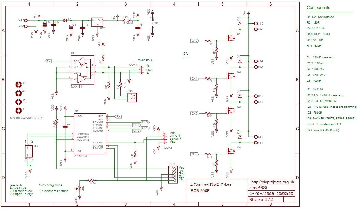
Fig.8/9 Install the four MOSFETs Q1,2,3,4 last. Observe antistatic handling precautions to avoid damage. Install and solder them into place one at a time. Solder the lead that connects to the copper ground plane first, then the lead at the opposite end and finally the centre lead.
Use solder to tin the copper tracks between the MOSFETs and the screw connectors to increase their current carrying capacity.
Fig. 12 Once the board has been assembled, apply power to the board and check that there is 5 volts between pins 1-14 of the IC1 socket and 5-8 of IC3 socket. Don’t install the ICs into the sockets until this has been checked and is correct.
Important:
If the board will be used with all four channels at high currents you must use solder to heavily tin all the copper tracks between the screw connectors and all the tracks feeding the MOSFETs
Connecting the board
The board can operate from voltages in the range 9-24 volts. The input voltage should be selected to suit the devices connected to the channel outputs.
Each channel can supply an absolute maximum of 3 amps*.
As there is no fault protection on the outputs you may need to use suitably rated in-line fuses depending on your particular application.
The red + channel connections are connected to + DC in and are all connected together on the PCB. The black channel wires are the MOSFET switched connections to ground.
Connection diagrams for LED arrays and relays are shown on the right. When used with relays ensure that the operating mode is set to static and not PWM.
For more detail: 4 Channel DMX512 Driver for PIC16F688