Searching for a reliable wireless solution for your project can be a real pain if you’re not familiar with current wireless standards, data rates and reliability. The Xbee Modules that we will use in this article are widely available, use a very reliable wireless transmission protocol and have sufficient datarates for most hobby projects.
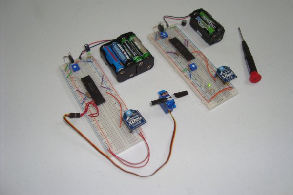
This article will show you how to build a basic wireless input and output system in the form of a single transmitter and single receiver. Communication will be one way to keep things simple with two xbee modules being used for the wireless link. In the end, a small trimpot will control the movement of a servo motor.
Purpose & Overview of this article
The goal for this article is to build a wireless transmitter that we can send input to and a wireless receiver that can recieve, translate and implement this input data to move a servo motor to a specific location.
To arrive at this goal, we will use two PIC Microcontrollers (one for the receiver and the transmitter) and two Xbee WiFi Modules (again, one for the receiever and the transmitter). The transmitter will have a standard trimpot circuit to input a variable analog voltage to the PIC’s A/D converter. The receiver will be connected to a servo motor that can be driven by a PWM signal.
PICkit2
2x PIC 18LF4520
2x LM317 Voltage Regulator
2x 5k Trimpot
4x 240Ω Resistors
2x 10kΩ Resistors
2x 3mm LEDs
2x 10uF Capacitors
2x 20 MHz Crystal
SIPs
2x Breadboard
Jumper Wire
2x 9v Connecter
2x Battery Holder
Parts List Details
The parts for both the transmitter and the receiver are listed above (notice a lot of duplicate 2x parts are listed. I’ll describe the more important parts in greater detail below.
PICkit2
This is the programmer that I use to load the firmware (software) that I create in Microchip’s MPLAB onto the PIC 18F4520 microcontroller. It’s a little expensive, but only comes as a one time cost. Once you have the programmer you can use it over and over to program almost every PIC that microchip makes.
PIC 18LF4520
Normally I use the PIC 18F4520 series PIC in my articles but since the Xbee Modules are not +5v compatible (Xbee Modules use +3.3v) I decided to use the ‘LF’ series of the PIC. The ‘LF’ series of the PIC can run on a +3.3v power supply, which means we can use the same power supply going to the Xbee Module and the PIC Microcontroller.
Xbee WiFi Module
These modules use the Xbee protocol (stack) for wireless communication, making them pretty darn reliable. The default speed setting for these modules is 9600 baud, so if you want to use these modules out of the box be sure your serial communication module is set to output at 9600 bps (as I do in this article).
LM317 Voltage Regulator
This voltage regulator is a variable type which means it can output 1.25 – 37v. We use a 240&Omega resistor and a 5k trimpot circuit, then vary the trimpot value until the LM317 outputs the +3.3v that we need.
Breadboard
Two standard sized breadboards are used to build the transmitter circuit and the receiver circuit. No secrets are surprises here, just a generic $10 breadboard.
Jumper Wire
Standard breadboard jumper wire is used to connect everything together. Jumper wire kits are pretty easy to find, or you can always just go to the store and buy a few feet of wire and cut your own jumper wire with a pair of wire cutters!
Schematic Overview
There are two schematics that we’ll look at to see how to build this transmitter/receiver system. The first one is the transmitter, with a variable trimpot input into RA0. The trimpot value will be sent out of the Tx pin of the PIC and to the Din pin of the Xbee module to send the signal wirelessly.
The receiver circuit, will receieve the transmitted signal through the Xbee module, out of the Dout pin and to the PIC’s Rx pin. The receiving PIC will then translate the data to movement coordinates for the servo motor.
Transmitter Schematic
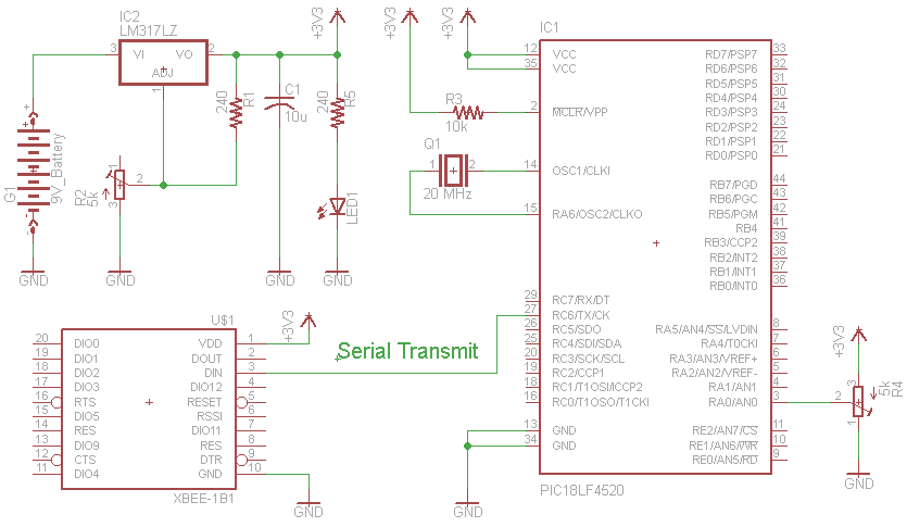
” Trimpot Input Into The PIC
The input we will give to the PIC’s will come from a standard trimpot’s output. The trimpot is tied to power and ground, with the middle pin being a variable voltage send to the PIC’s A/D converter on pin RA0.
“Xbee Module Wireless Output
The PIC will then translate this input to an integer of value 0-50 and send it via the PIC’s serial communication module at 9600 BPS to the Xbee’s Din pin.
For more detail: Xbee Wireless Servo Control using PIC18LF4520