Summary of Vehicle Tracking System Through GPS-GSM Modules
This article guides beginners in building a real-time vehicle tracking system using GSM and GPS modules. The author shares personal experiences, emphasizing common mistakes and safety precautions. The project connects a device to a webserver to transmit coordinates for viewing on a platform.
Parts used in the Vehicle Tracking System:
- GSM Module (SIM800L)
- GPS Module (Ublox NEO6M)
- Microcontroller (Arduino Uno or Nano)
- Battery (18650 cell)
- Battery holder
- DC-DC Boost Converter Step Up Module 5V
- Wires, soldering iron, breadboard
![]()
So you have got a GSM module lying around like me? Also a GPS-tracker?
We think the same!
In this instructables, I will try to guide you how to accomplish your goal from a newbie’s perspective.
As I had no previous electrical engineering knowledge (to be honest, the project doesn’t need that much,but nah), and had no clue how to make a device which pumps data real-time to a webserver, I encountered numerous problems. Still, I eventually managed to get things to work.
So, in this tutorial, I want to emphasise the mistakes a starter can make, and build-up the project accordingly.
Remember: Always be careful while you work with electricity!
NOTE: I am not professional. The code may be not sophisticated enough for all of your need. The project is intented to be a “hobby project”, but! it worked for me. And if it worked for me, it would work for you too!
Step 1: Prerequisites
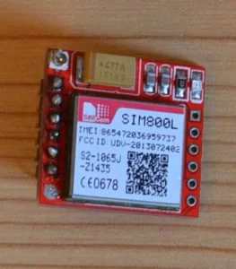
GSM MODULE – SIM800L
- Pretty tiny, easy-to-use
- Capable of using mobile internet (GPRS)
- Cheap
GPS MODULE – Ublox NEO6M
- Also small
- Handles its job very well
A microcontroller – can be anything – you could use the famous Arduino Uno or the Nano to free up some space
Battery – I used a 18650 cell as the main, and only power source (Nominal 3.7V)
Battery holder – why? – because soldering an 18650 battery is pretty dangereous because of the heat.
DC-DC Boost Converter Step Up Module 5V – Must have, since the Arduino I used needs 5V
Tools, basic stuff which can come in handy:
Wires, soldering iron, breadboard for testing
Step 2: Main Concept
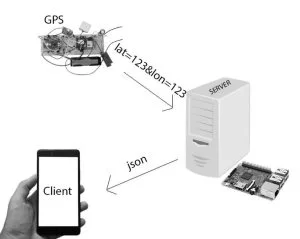
The main concept of the system is the following:
It consists of 3 parts:
- A device – which have the proper GPS-Coordinates and can connect to a server remotely and send data to it
- A webserver – which can receive incoming data – store it – and serve other clients
- The platform – where we can view the coordinates – Ideally it should be now a mobile application, or a website
Source: Vehicle Tracking System Through GPS-GSM Modules
- What are the prerequisites for this project?
You need a GSM module like SIM800L, a GPS module like Ublox NEO6M, a microcontroller such as Arduino Uno or Nano, a 18650 battery, a battery holder, a DC-DC Boost Converter 5V, and basic tools. - Why is a battery holder recommended over soldering directly?
Soldering an 18650 battery directly is dangerous due to the heat involved. - Can I use any microcontroller for this project?
Yes, you can use anything like the famous Arduino Uno or the Nano to free up some space. - What is the main concept of the system?
The system consists of a device with GPS coordinates that sends data to a webserver, which stores it and serves clients on a platform. - Does this project require professional electrical engineering knowledge?
No, the project does not need much electrical engineering knowledge, though the author had none initially. - Is the code provided in the article sophisticated?
The code may not be sophisticated enough for all needs as the project is intended to be a hobby project. - What type of platform is ideal for viewing the coordinates?
Ideally, the platform should be a mobile application or a website. - What is the nominal voltage of the battery used?
The 18650 cell used has a nominal voltage of 3.7V. - Why is a DC-DC Boost Converter Step Up Module 5V necessary?
It is a must-have because the Arduino used needs 5V power.