Summary of USB THERMOMETER CIRCUIT CCS C PIC18F4550
This article details a USB thermometer project using the PIC18F4550 microcontroller and CCS C compiler. The system reads temperature data from a DS1820 sensor connected to the RA5 pin and transmits it to a computer via USB. Although the author notes some initial challenges with USB communication compared to RS232, they successfully implemented a basic driver configuration with Vendor ID 0x1111 and Product ID 0x1111 to display readings on a PC.
Parts used in the USB Thermometer Circuit:
- PIC18F4550 Microcontroller
- DS1820 Temperature Sensor
- USB Port
- RA5 Pin
- usb_driver.h File
- C# Form Application
Hi All You Guys. How long have you been working on CCS C. CCS will be able to see my level, so it is no longer something to do after arrival. In this article,… Electronics Projects, USB Thermometer Circuit CCS C PIC18F4550 “microchip projects, microcontroller projects, “
Hi All You Guys.
How long have you been working on CCS C. CCS will be able to see my level, so it is no longer something to do after arrival.
In this article, I made a small application on the USB communication pic18f4550. I really wanted to deal with the USB. A little uğraştırsada due to the short time for plenty of sample applications around USB thing figured out. I think there’s a common idea in dealing with USB. Because that I haven’t read about this article or the article. Well, first a couple of application korkutsada the USB after the eye really is different from rs232 communication in terms of convenience.
Now, my application
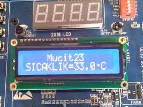
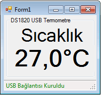
The system is very simple. Depending on the temperature the temperature sensor DS1820 Sıcaklık Sensorü RA5 pic18f4550, PIN information, and sends it to the computer via the USB port. For now only sends to the computer. I’m a little more for the novice yet C # form and showed the form only in order to show the temperature of the communication with the pic.
USB thermometer proteus isis circuit diagram
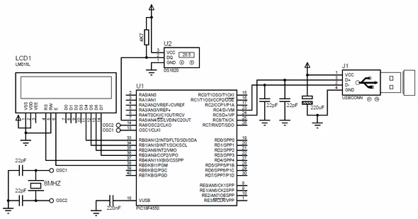
Vendor ID and ProductID information in the file is determined usb_driver.h. I did both: 0x1111 hex.
Source: USB THERMOMETER CIRCUIT CCS C PIC18F4550 all files : usb-thermometer-circuit-ccs-c-pic18f4550.rar
- How is the temperature sensor connected?
The DS1820 sensor connects to the RA5 pin of the PIC18F4550. - What communication method does the system use?
The system sends data to the computer via the USB port. - Which programming language is used for the microcontroller?
The project utilizes CCS C for the application code. - What are the Vendor and Product IDs set to?
Both the Vendor ID and Product ID are determined as 0x1111 hex in the usb_driver.h file. - Does the system currently receive commands from the computer?
No, the system only sends temperature data to the computer for now. - What software displays the temperature on the PC?
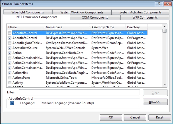
A simple C# form application was created to show the temperature readings. - Is USB communication considered more convenient than RS232?
Yes, the author notes that USB differs from RS232 in terms of convenience.