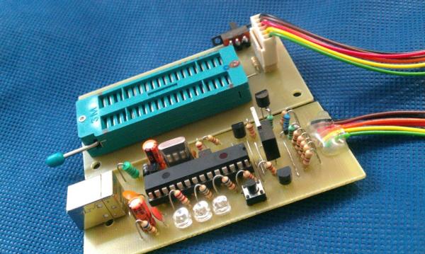
Summary of USB PIC Programmer : PICKit2 using pic microcontoller
This article discusses a modified version of Microchip's PICKit2 USB-based ICSP programmer designed for easier and more reliable microcontroller programming. The modification simplifies the original hardware by removing unnecessary components, adding an ICSP-to-ZIF converter for flexibility, supporting only 5V PICs, replacing bipolar transistors with MOSFETs, and switching to a USB-B connector. The device is powered via USB, uses a PIC18F2550 microcontroller, and includes a DC-DC buck converter to provide the necessary programming voltage.
Parts used in the Modified PICKit2 USB PIC Programmer:
- PIC18F2550 USB Microcontroller
- External Crystal Oscillator (X1)
- Capacitors (C1, C2, C3, C4)
- Inductor (L1)
- MOSFET Transistor (Q1)
- Diode (D1)
- ICSP to ZIF Socket Converter
- USB-B Connector
Microchip’s PICKit2 is much more comfortable,reliable and powerful than the other programmers that we can find all over internet. It is a USB based ICSP (In Circuit Serial Programming) programmer. Since it is a first release, Microchip published all the resources of PICKit2 public, which includes hardware schematics and all source code of softwares used. Through this any one can add features, fix bugs and modify source code.
 Documents and other supporting files of PICKit2 are available at Microchip’s Website.
We have simplified the hardware schematics of PICKit2 by removing all unnecessary devices from it and ICSP to ZIF converter is also added for easier programming. The main differences between the modified PICKit2 and Original PICKit2 are:
1. ICSP to ZIF converter is added for easier programming, thus we can use ICSP or ZIF socket according to our needs.
2. It supports only 5V PIC’s, thus 3.3V devices a small additional circuit to convert 5V to 3.3V.
3. Two 24C512 EEPROM’s used only for programmer-to-go function in the Original PICKit2 were omitted. The Programmer-to-go function is not an important feature for a electronics hobbyist.
4. Bipolar transistors used in Original PICKit2 are replaced by MOSFETs, thus minimal additional components are required.
5. The mini USB connector is replaced by commonly available USB-B connector.
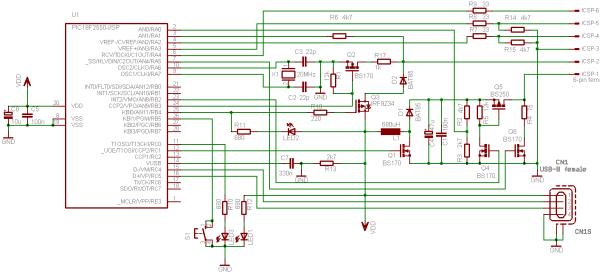
USB PIC Programmer PICKit2 Modified Circuit Diagram
PICKit2 is a USB powered device, that is it gets power from PC USB +5V power supply. USB microcontroller PIC18F2550 is the soul of the PICKit2. The USB Data+ and Data- from PC are connected to the D+ and D- pins of the PIC182550. The built-in-clock generator of pic uses external crystal oscillator X1, C2 and C3 to ensure the correct system clock rate. The inductor L1, MOSFET Q1, diode D1, capacitors C1 and C4 forms a DC-DC converter (Buck Converter) which converts 5V from PC to 12V, which to be applied to MCLR/VPP pin of a microcontroller at the time of programming.
For more detail: USB PIC Programmer PICKit2

