Summary of Unipolar Stepper Motor Control Example with PIC12F1822 Microcontroller
This article demonstrates driving a 5V unipolar stepper motor with a PIC12F1822 microcontroller and ULN2003 driver in three modes: one-phase (single-coil full step), two-phase (dual-coil full step), and half-step. It explains wiring, uses the PIC internal oscillator, and a potentiometer on AN0 to control speed and direction. CCS C example code for one-phase mode and discussion of two-phase mode sequences are provided.
Parts used in the Unipolar Stepper Motor Control Example with PIC12F1822:
- 5V unipolar stepper motor (5-wire)
- Microchip PIC12F1822 microcontroller
- ULN2003 motor driver IC
- Potentiometer connected to AN0
- Power supply (5V for motor and appropriate supply for PIC)
- Wiring and connectors
- PCB or breadboard for assembly
This topic shows how to drive 5V unipolar stepper motor in 3 modes one-phase, two-phase and half step. The microcontroller used in this project is Microchip PIC12F1822 and the motor drive circuit is ULN2003.
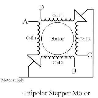
Usually the unipolar stepper motor has 5 wires one for motor supply and the other for coils. This motor has 4 coils and they are connected as shown in the figure below:
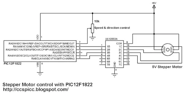
Unipolar Stepper Motor Control Example with PIC12F1822 circuit:
All the three control modes have the same circuit schematic as shown below.
Here PIC12F1822 uses its internal oscillator.
The potentiometer connected to AN0 is used to control motor speed and direction of rotation.
Unipolar Stepper Motor Control Example with PIC12F1822 CCS C code:
One Phase On Mode (Full Step mode):
In one phase control mode only one coil is energized at once. This mode produces smooth motion with low power consumption. Control sequence has 4 steps as shown in the table below:
CCS C code:
/* Unipolar stepper Motor control using PIC12F1822 (one-phase full step mode) CCS PIC C code
   http://ccspicc.blogspot.com/
   [email protected]
*/

#include <12F1822.h>
#fuses NOMCLR INTRC_IO PLL_SW
#device ADC = 8                                       // Set ADC resolution to 8-bit
#use delay(clock=32000000)
#use fast_io(A)

unsigned int8 i, step_number = 0;
void stepper(int8 step){
  switch(step){
    case 0:
      output_a(0b100000);
    break;
    case 1:
      output_a(0b010000);
    break;
    case 2:
      output_a(0b000100);
    break;
    case 3:
      output_a(0b000010);
    break;
  }
}
void main() {
  setup_oscillator(OSC_8MHZ | OSC_PLL_ON);            // Set internal oscillator to 32MHz (8MHz and PLL)
  output_a(0);
  set_tris_a(1);                                      // Configure RA0 pin as input
  setup_adc(ADC_CLOCK_DIV_32);                        // Set ADC conversion time to 32Tosc
  setup_adc_ports(sAN0);                              // Configure AN0 pin as analog
  set_adc_channel(0);                                 // Select channel AN0
  while(TRUE){
    output_a(0);
    i = read_adc();                                   // Read from AN0 and store in i
    while(i >= 128){                                  // Move motor in direction 1
      step_number++;
      if(step_number > 3)
        step_number = 0;
      stepper(step_number);
      delay_ms(257 - i);
      i = read_adc();                                 // Read from AN0 and store in i
    }
    while(i < 128){                                   // Move motor in direction 2
      if(step_number < 1)
        step_number = 4;
      step_number--;
      stepper(step_number);
      delay_ms(i + 2);
      i = read_adc();                                 // Read from AN0 and store in i
    }
  }
}
Two Phases On Mode (Alternate Full Step mode):
In two-phase mode two coils are energized. This mode produces high torque but its motion is not smooth like the one phase mode. The following table shows this mode sequence:
Read more: Unipolar Stepper Motor Control Example with PIC12F1822 Microcontroller
- What microcontroller is used in the project?
The project uses the Microchip PIC12F1822 microcontroller. - What driver IC is used to drive the stepper motor?
The motor drive circuit uses the ULN2003. - How many wires does the unipolar stepper motor have?
Usually the unipolar stepper motor has 5 wires: one for motor supply and four for coils. - What control modes are demonstrated for the stepper motor?
The article demonstrates one-phase (full step), two-phase (alternate full step), and half-step modes. - How is motor speed and direction controlled?
A potentiometer connected to AN0 of the PIC12F1822 is used to control motor speed and direction. - Does the PIC12F1822 use an external oscillator in this project?
No, the PIC12F1822 uses its internal oscillator configured with PLL to run at 32MHz. - What is the advantage of one-phase on mode described?
One-phase on mode produces smooth motion with low power consumption. - What is the characteristic of two-phase on mode?
Two-phase on mode produces higher torque but its motion is less smooth than one-phase mode.