I’ve always wanted a better way of seeing close up when carrying out soldering or working with PCB’s or small components, I’ve tried the visor magnifiers and never been to happy as your head is backwards and forwards trying to focus and you have to get too close to the workpiece in turn breathing in more fumes from soldering.
Another thing is the lighting when working like this, and shadows are not a good thing, my main light being above my head and causes shadows.
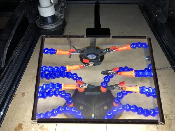
My aim here is to create the Ultimate workstation, using 6 way helping hands, a fan to take the soldering fumes away, for magnification I will be using an A4 x2 Magnifying sheet using 12v LED’s around the perimeter of the magnifier for Illumination, and a gooseneck arm for easy positioning of the magnifier, the mount for the magnifier to the gooseneck arm will be designed in Fusion 360 and 3D Printed, with a simple on/off switch to turn power on and off.
I will be using the CNC machine to cut the slot for the power and holes for the fan and Gooseneck cabling, and will be wearing the necessary PPE throughout this operation, to Include Ear and Eye protection and the correct rated dust mask.
On with the Light Show———–>
Supplies
A4 x2 Magnifying sheet. Purchased online.
Gooseneck arm and base Purchased online
LED Adhesive backed Strip lighting 12v, I already had
15mm MDF for the Base, Already had form the plant stand build
12v Power connecter screw terminal Female, Already had
12v Power supply, Had a used one, Ideal
On/Off Rocker switch, Already had
CA Glue Already had
Soldering Iron and Lead free solder. Already had
1.5mm pvc sheathed/ Unsheathed wire Already had
Heat shrink Already had
Step 1: The First Steps
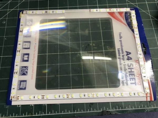
I had a general idea of how I was going to build this light and started off by cutting and sticking the LED’s to the A4 Magnifier, these were orientated around the perimeter of the magnifier so all the +’s and -‘s matched up and being careful to leave a space for the gooseneck adapter, I started with pvc sheathed cable to join the LED strips but the lengths were that small that it made it difficult to strip the cable ends, so I opted for unsheathed which is fine as long as they are kept apart which in this case, they were.
I then soldered all the joints and for the supply to the LED strip I connected 2 lengths of 1.5mm white PVC sheathed cable enough to thread through the Gooseneck and marked these for + and – I tested the cables at this point and apart from sorting a bad joint all worked well, and creates a good light.
Its worth bearing in mind that these LED’s are not WS1282b that type have 3 terminals and they are addressable and need a microprocessor to run them, the connections are+,- and a signal or data cable, the 12v Led’s I am using have Positive + and Ground – only, and can be run off a 12v Power Supply/Walwart and switched.
I needed some means of connecting the Gooseneck to the A4 Magnifier sheet and came up with a design in Fusion 360, this adapter will be 3D printed.
Next step.. The adapter.
Step 2: Fusion 360 Adapter Design
The adapter in my head would be of the type to grab the magnifier within a slot on the adapter and below the slot there would be a hole to accommodate the cables from the LED strip to the MDF base via the Gooseneck arm.
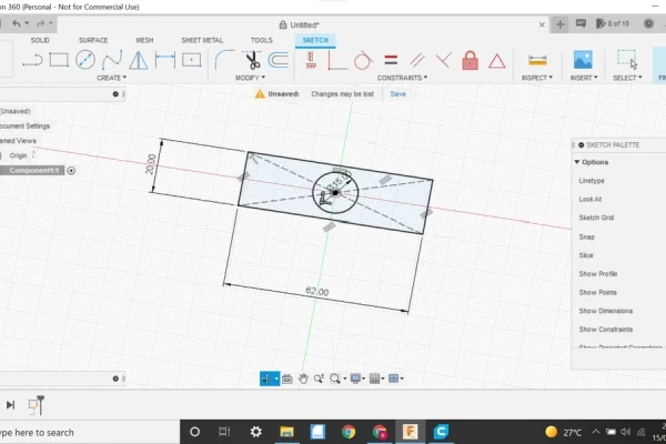
In Fusion I created a new Component then new sketch selecting the Top Plane for the sketch, I started off with a centre rectangle and created a rectangle of 62 x 20, a 15mm hole was added in the centre of this and extruded to 12mm this will allow us to screw the gooseneck into the adapter, we now need to create material so we can accommodate the Magnifying sheet so a further 7mm was added, another sketch was started and selecting the newly extruded face, a 2 Point rectangle was used dragging to opposite corners, this sketched was then extruded 7mm and the Join tab selected.
To make a slot in this, we select the newly extruded Face, and create a centre rectangle of 62mm x 2mm the 2mm dimension is the thickness of the A4 Magnifying sheet, we want a very snug fit so no offset was used on this occasion.
The slot was extruded -6.4 to accommodate the sheet.
We now need to form a hole through the face below the slot into the cavity where the gooseneck arm entry hole for the cables is.
To form this hole we are going to create a 5mm centre hole on the top face, we then extrude this 20mm and make it a new component, if we right click on this component 2 on the left side of the page and click move/copy we can, using various views manipulate it into a position between the face and the cavity, this will allow us to push the LED cables through the hole and into then through the Gooseneck arm into the base.
To finalise, 2mm fillets were added to the edges of the adapter.
With cables Installed I pushed the magnifying sheet into the slot using some pressure and it fitted perfectly.
To the base and electrics.
Step 3: Base, Electrics and Testing.
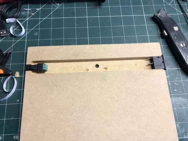
I already had the base which was handy, it was a spare from some plant stands I had already completed for my sister, using the CNC machine I created a simple 8mm hole for the cables from the Gooseneck and a slot to accommodate the cables from the supply in and the on/off switch, I screwed the Gooseneck into position and then I drilled by hand a further 5mm hole for the fan which I had forgotten about, The helping hands came with a little 5v USB Fan, I swapped this for a larger 12v fan I already had, I had to extend the cables a bit, I then cut away the ends of the slot to accommodate both the power connector and the On/Off switch, these are just held in place using CA Glue, The – on the connector is the ground to both the LED’s and the Fan, and the + goes to the centre connector on the switch, and from the adjacent connector on the switch is power to LED’s and Fan Switched supply.
Time to test:
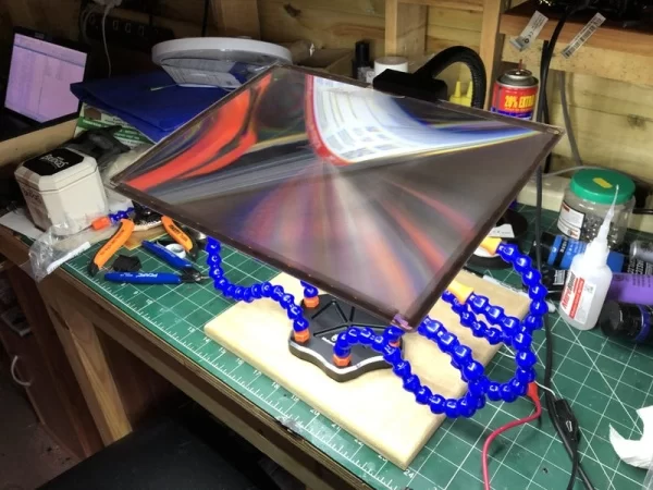
I found a 12v Power supply and plugged it in, flicked the switch on and there was light, I sat the helping hands on the MDF base and lowered the magnifier, wow! this really works well, and being an A4 sheet I can see everything I want to see, This will make soldering etc so much easier.
I drilled 2 holes in the helping hands base and screwed it to the base to stop any movement and that’s about it completed, would be good to get some rubber feet for the base to stop any movement altogether.
I was going to paint the Base Black but I thought what’s the point it looks ok as it is.
Assumptions:
Step 4: Magnifier Light Assumptions
All in all I’m pretty impressed with the outcome of the Magnifier Light, It works really well, the Gooseneck arm makes for a rigid holder for the Magnifying sheet and is easily manoeuvred into different positions.
The whole thing does what I wanted it to do and coupled up with the helping hands is an awesome compact piece of Kit, The Fan will keep fumes away as well, which is a bonus.
The uses are endless.
I hope you enjoyed this Instructable as always and thanks for looking!
Source: Ultimate Soldering LED Light With A4 Sheet Magnifier