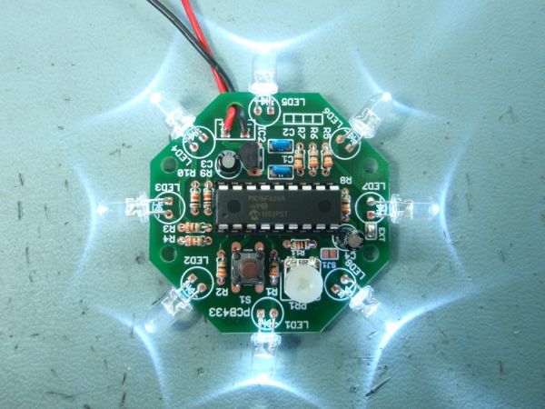
Summary of UFO round LED Chaser with speed control for PIC16F628A
This updated UFO LED Chaser uses PIC16F628A firmware PWM LED Chaser v3.0.0 to drive 8 LEDs with 4 intensity levels, variable chase speed, multiple sequences and modes, and non-volatile sequence memory. A software oscillator (PR1/C4) enables adjustable speed via a solder-bridge selectable EXT option; the kit includes parts and a preprogrammed HEX plus source code for custom sequences.
Parts used in the UFO LED Chaser:
- PIC16F628A microcontroller (pre-programmed)
- LED1 through LED8 (8 LEDs)
- R1 through R8 (LED current limiting resistors)
- R9 (switch S1 pull-up resistor)
- R10 (MCLR pull-up resistor)
- R11 (1K series resistor with PR1)
- PR1 (variable resistor/potentiometer for speed control)
- C1 (5V decoupling capacitor)
- C3 (regulator stability capacitor)
- C4 (oscillator timing capacitor)
- IC2 LM2931-5.0 5V voltage regulator
- Switch S1 (mode/control switch)
- PCB with solder pads and jumpers (EXT, SJ1, MODE)
- Power input solder points (+ and -)
- Optional: breadboard or stripboard if not using PCB
Description
This is an updated version of the UFO LED Chaser project, revised to use the PWM LED Chaser code version 3.0.0 with support for variable chase speed. The basic LED chaser ‘engine’ firmware is the same as that used with the 481/483 LED chaser projects also on this site. The only difference is the sequence data used to create the programmer ready .HEX file. This has been modified to include chase effects that suit the circular arrangement of LEDs.
Unlike many simple LED chaser projects the design presented here provides 8 LEDs directly driven from the PIC along with a single mode control switch and speed adjust control. The firmware elsewhere on this page drives the LEDs with a 5 bit PWM signal providing each of the 8 LED channels with four levels of intensity; off, dim, mid and bright. A number of sequences are programmed into the firmware to provide some interesting visual effects and chase sequences.
The software has sequential, random and manual sequence run modes and manual advance to the next sequence in any mode. The selected sequence and mode are also saved to non-volatile memory so it will always restart in the selected mode.
The design is deliberately simple with each LED being directly driven from a PIC I/O pin. You can use it with different sized LEDs and mixed colours. While it works well as a simple LED chaser, thinking outside the box it can be used to add effects to toys and models and even accessorize fancy dress costumes. See FAQ
A solder pad jumper on the PCB selects between fixed speed chaser using internal timing or variable chase speed adjustable using the on-board variable resistor. The adjustable chase speed option makes it ideal for use in a wide range of applications. The kit 433K includes all parts needed to build the variable speed chaser.
The firmware pre-programmed into the PIC16F628A supplied with the kit includes over 34 chase effects and sequences. If you’re interested in PIC micros and programming and want to modify the sequences or create new ones, the source code and programmer ready HEX file is provided at the bottom of this page.
The heart of the LED chaser is the PIC 16F628A microcontroller, IC1. The program that runs on this chip controls the LEDs attached to the output port pins. Resistors R1 thru R8 limit the current through LED1 – LED8 to a safe level that won’t damage the PICs I/O ports or LEDs. Resistor R9 provides a pull-up for the input connected to switch S1. R10 holds the PICs MCLR reset signal high.
The variable resistor PR1 along with C4 are used to create a software oscillator. C4 is charged and discharged via PR1 from port B0 output. The input on Port A7 is monitored by the firmware, when the input goes high port B0 is driven low to discharge C4. When Port A7 goes low, port B0 is driven high to charge C4. An important requirement is the use of a Schmitt trigger input buffer on Port A7 input pin which provides the necessary hysteresis to make the software oscillator work. This oscillator is then used to provide the clock for the chaser timing and since the speed is controlled by the rate C4 charges through PR1 the chaser speed can be controlled by adjusting PR1. A 1K0 resistor, R11 is placed in series with PR1 to set the maximum chase speed when PR1 is adjusted to minimum resistance.
Capacitor C1 is used to decouple the 5 volt power supply to the PIC. If you’re building the circuit on a breadboard or stripboard you should ensure it is located close to the PICs Vdd connection (pin 14 ).
Power is supplied to the circuit via the +/- solder points. The voltage regulator, IC2 is a LM2931-5.0, low-drop-out regulator and will maintain regulation with an input voltage down to 5.8 volts. Input voltage for the LED chaser should be between 6 volts and 14 volts to ensure power dissipation remains within limits. The LM2931-5.0 regulator is designed for battery powered and automotive applications and includes internal current limiting, thermal shutdown, as well as reverse battery connection without damage to itself or the circuit behind it. Capacitor C3 is important and must be fitted to prevent instability of the regulator output
Typical current drawn by the circuit with all LEDs on is only around 80mA; with all LEDs off it is under 5mA.
Notes:
- The latest high brightness LEDs are very bright even with 330R current limiting resistors. However, if you do need to change these resistors for some reason take into account the maximum current that the on-board voltage regulator can deliver is 100mA.
- EXT solder bridge jumper.
When left open the chaser runs at a fixed speed using the internal sequence timing data.
When closed (bridged with solder on the PCB) the chaser uses the software controlled oscillator for timing, the frequency is adjusted using PR1 which in turn controls the chase speed.
If you leave the ‘EXT’ jumper open, you can omit PR1, R11 and C4. The circuit and firmware will operate correctly using the internal timing data.
- The jumpers marked ‘SJ1‘ and ‘MODE‘ are not currently used. Do not bridge them with solder.
For more detail: UFO round LED Chaser with speed control for PIC16F628A
- How many LEDs does the UFO LED Chaser directly drive?
It directly drives 8 LEDs from the PIC I/O pins. - Can the chase speed be adjusted?
Yes, chase speed can be adjusted using the on-board variable resistor PR1 when the EXT jumper is bridged. - Does the kit include a preprogrammed microcontroller?
Yes, the PIC16F628A supplied with the kit is preprogrammed with over 34 chase effects and sequences. - What happens if the EXT jumper is left open?
If EXT is open the chaser runs at a fixed speed using internal timing and PR1, R11, and C4 can be omitted. - What voltage range should be supplied to the chaser?
Input voltage should be between 6 volts and 14 volts for safe operation and regulator dissipation limits. - How many intensity levels does each LED channel have?
Each LED channel has four intensity levels: off, dim, mid and bright via 5-bit PWM implementation. - Is the selected sequence preserved after power off?
Yes, the selected sequence and mode are saved to non-volatile memory so it restarts in the selected mode. - What is the typical current draw with all LEDs on?
Typical current with all LEDs on is around 80 mA; with all LEDs off it is under 5 mA. - What regulator is used and why?
The LM2931-5.0 low-drop-out regulator is used for battery and automotive suitability, with internal current limiting and thermal shutdown. - Can the firmware be modified?
Yes, the source code and programmer-ready HEX file are provided for modifying or creating new sequences.