
Summary of Thermal Printer interfacing with PIC16F877A
This tutorial demonstrates interfacing a CSN A1 thermal printer with a PIC16F877A microcontroller. The system uses a tactile switch to trigger printing and an LED to indicate status via UART communication at 9600 baud. The project highlights the printer's requirement for a 5V 2A power supply due to high current draw during head heating.
Parts used in the Thermal Printer CSN-A1 Interfacing with PIC16F877A:
- Breadboard
- Hook up wires
- PIC16F877A Microcontroller
- 2pcs 33pF ceramic disc capacitor
- 680R resistor
- Any color led
- Tactile switch
- 2pcs 4.7k resistors
- Thermal Printer CSN A1 with paper roll
- 5V 2A rated power supply unit
Thermal printer is often referred as receipt printer. It is widely used in restaurants, ATM, shops and many other places where receipts or bill is required. It is a cost-effective solution and very handy to use from the user’s side as well as from the developer’s side. A thermal printer uses a special printing process which uses thermochromic paper or thermal paper for printing. The printer head is heated at a certain temperature that when the thermal paper passes from the print head, the paper coating turns black in the areas where the printer head is heated.
In this tutorial, we will interface a thermal printer CSN A1 with widely used PIC microcontroller PIC16F877A. Here in this project, a thermal printer is connected across PIC16F877A and a tactile switch is used to start the printing. A notification LED is also used to notify the printing status. It will glow only when the printing activity is going on.

Printer Specification and Connections
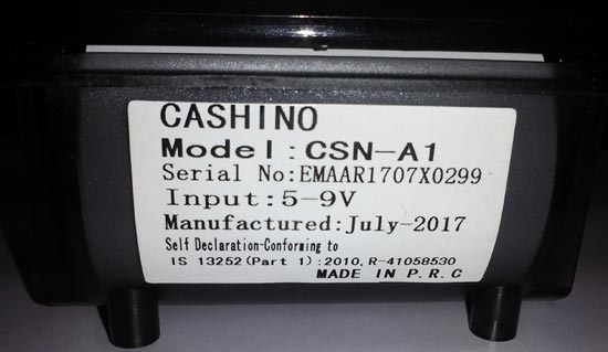
We are using CSN A1 Thermal Printer from Cashino, which is available easily and the price is not too high.
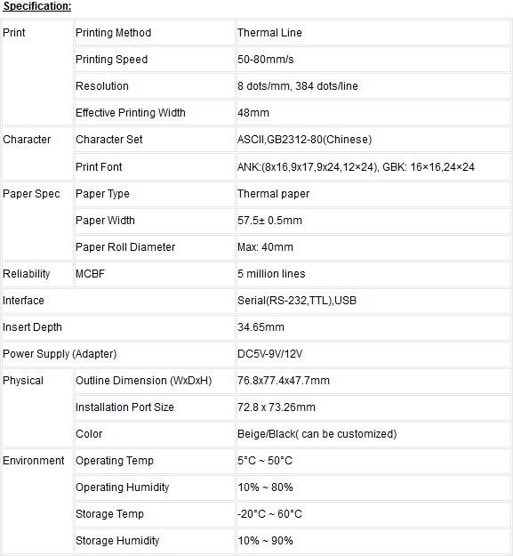
If we see the specification on its official website, we will see a table which provides the detailed specifications-
On the back side of the printer, we will see the following connection-
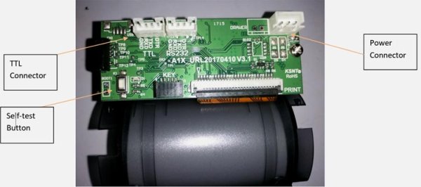
The TTL connector provides the Rx Tx connection to communicate with the microcontroller unit. We can also use the RS232 protocol to communicate with the printer. The power connector is for powering the printer and the button is used for printer testing purpose. When the printer is being powered, if we push the self-test button the printer, will print a sheet where specifications and sample lines will be printed. Here is the self-test sheet-
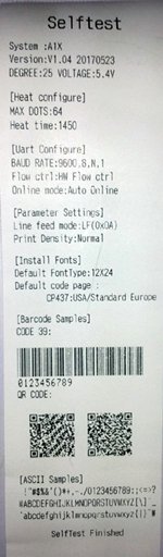
As we can see the printer use 9600 baud rate to communicate with the microcontroller unit. The printer can print ASCII characters. The communication is very easy, we can print anything by simply using UART, transmitting string or character.
The printer needs a 5V 2A power supply for heating the printer head. This is the drawback of the thermal printer as it takes huge load current during the printing process.
Prerequisites
To make the following project, we need the following things:-
- Breadboard
- Hook up wires
- PIC16F877A
- 2pcs 33pF ceramic disc capacitor
- 680R resistor
- Any color led
- Tactile switch
- 2pcs 4.7k resistors
- Thermal Printer CSN A1 with paper roll
- 5V 2A rated power supply unit.
Circuit Diagram and Explanation
Schematic for controlling printer with PIC Microcontroller is given below:
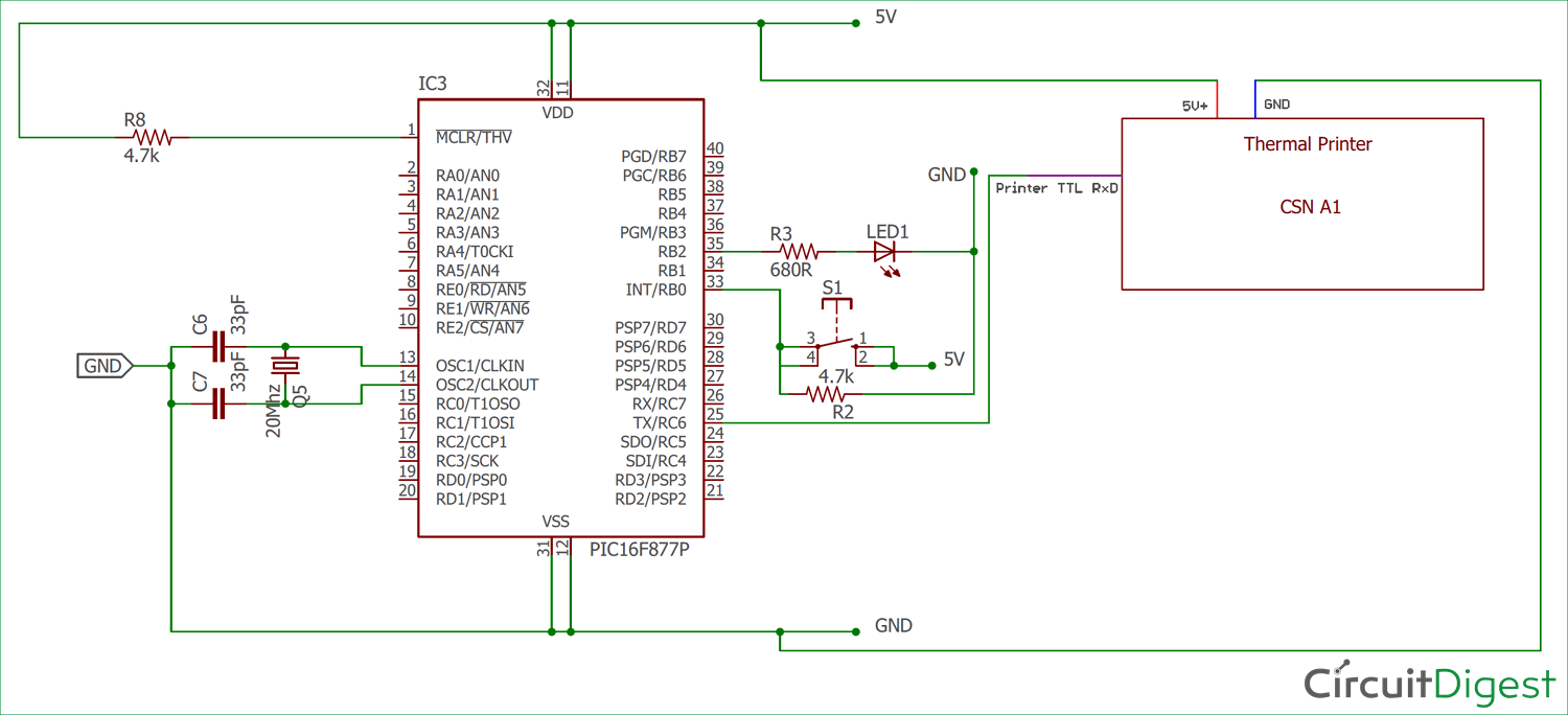
Here we are using PIC16F877A as microcontroller unit. A 4.7k resistor is used to connect MCLR pin to the 5V power supply. We have also connected an external oscillator of 20 MHz with 33pF capacitors for the clock signal. A notification LED is connected across RB2 port with 680R led current limiting resistor. The Tactile switch is connected across RB0 pin when the button is pressed it will provide Logic High otherwise the pin will receive Logic low by the 4.7k resistor.
The printer CSN A1 is connected using the cross configuration, Microcontroller Transmit pin is connected with the printer’s Receive pin. The printer also connected with the 5V and GND supply.
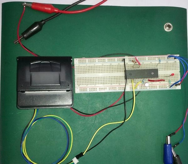
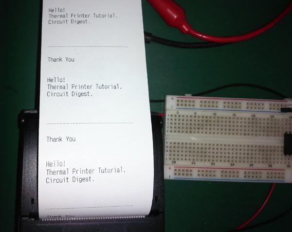
We constructed the circuit in a breadboard and tested it.
Code Explanation
The code is pretty simple to understand. Complete code for interfacing Thermal Printer with PIC16F877A is given at the end of article. As always, we first need to set the configuration bits in the PIC microcontroller.
// PIC16F877A Configuration Bit Settings
// 'C' source line config statements

// CONFIG
#pragma config FOSC = HS        // Oscillator Selection bits (HS oscillator)
#pragma config WDTE = OFF       // Watchdog Timer Enable bit (WDT disabled)
#pragma config PWRTE = OFF      // Power-up Timer Enable bit (PWRT disabled)
#pragma config BOREN = ON       // Brown-out Reset Enable bit (BOR enabled)
#pragma config LVP = OFF         // Low-Voltage (Single-Supply) In-Circuit Serial Programming Enable bit (RB3/PGM pin has PGM function; low-voltage programming enabled)
#pragma config CPD = OFF        // Data EEPROM Memory Code Protection bit (Data EEPROM code protection off)
#pragma config WRT = OFF        // Flash Program Memory Write Enable bits (Write protection off; all program memory may be written to by EECON control)
#pragma config CP = OFF         // Flash Program Memory Code Protection bit (Code protection off)
After that, we defined system hardware related macros and used eusart1.h header file for eusart related hardware control. The UART is configured at 9600 Baud rate inside the header file.
#include <xc.h>
#include "supporting_cfile\eusart1.h"
/*
 * System hardware related macros
 */
#define _XTAL_FREQ 200000000 //Crystal Frequency, used in delay routine
#define printer_sw PORTBbits.RB0 //this macro is for defining the printing switch
#define notification_led PORTBbits.RB2
void system_init(void);
In the main function, we first checked the ‘button press’ and also used switch debounce tactics to eliminate the switch glitches. We have created a if statement for ‘button pressed’ condition. First the led will glow and the UART will print the strings. Custom lines can be generated inside the if statement and can be printed as a string.
void main(void) {
    system_init();
    while(1){
        if(printer_sw == 1){ //switch is pressed
            __delay_ms(50); // debounce delay
            if (printer_sw == 1){ // switch is still pressed
                notification_led = 1;
                put_string("Hello! \n\r");//Print to Thermal printer
                __delay_ms(50);
                put_string("Thermal Printer Tutorial.\n\r");
                __delay_ms(50);
                put_string("Circuit Digest. \n\r");
                __delay_ms(50);
                put_string ("\n\r");
                put_string ("\n\r");
                put_string ("\n\r");
                put_string ("---------------------------- \n \r");
                put_string ("Thank You");
                put_string ("\n\r");
                put_string ("\n\r");
                put_string ("\n\r");
                notification_led = 0;
                }
            }
        }
    }
Complete Code and working Video is given below.
/*
* File: main.c
* Project: Thermal Printer CSN-A1 Interfacing with pic16F877A
* Author: Sourav Gupta.
* Created on 08 September 2018, 16:15
*/
// PIC16F877A Configuration Bit Settings
// ‘C’ source line config statements
// CONFIG
#pragma config FOSC = HS // Oscillator Selection bits (HS oscillator)
#pragma config WDTE = OFF // Watchdog Timer Enable bit (WDT disabled)
#pragma config PWRTE = OFF // Power-up Timer Enable bit (PWRT disabled)
#pragma config BOREN = ON // Brown-out Reset Enable bit (BOR enabled)
#pragma config LVP = OFF // Low-Voltage (Single-Supply) In-Circuit Serial Programming Enable bit (RB3/PGM pin has PGM function; low-voltage programming enabled)
#pragma config CPD = OFF // Data EEPROM Memory Code Protection bit (Data EEPROM code protection off)
#pragma config WRT = OFF // Flash Program Memory Write Enable bits (Write protection off; all program memory may be written to by EECON control)
#pragma config CP = OFF // Flash Program Memory Code Protection bit (Code protection off)
#include <xc.h>
#include “supporting_cfile\eusart1.h”
/*
* System hardware related macros
*/
#define _XTAL_FREQ 200000000 //Crystal Frequency, used in delay routine
#define printer_sw PORTBbits.RB0 //this macro is for defining the printing switch
#define notification_led PORTBbits.RB2
void system_init(void);
void main(void) {
system_init();
while(1){
if(printer_sw == 1){ //switch is pressed
__delay_ms(50); // debounce delay
if (printer_sw == 1){ // switch is still pressed
notification_led = 1;
put_string(“Hello! \n\r”);//Print to Thermal printer
__delay_ms(50);
put_string(“Thermal Printer Tutorial.\n\r”);
__delay_ms(50);
put_string(“Circuit Digest. \n\r”);
__delay_ms(50);
put_string (“\n\r”);
put_string (“\n\r”);
put_string (“\n\r”);
put_string (“—————————- \n \r”);
put_string (“Thank You”);
put_string (“\n\r”);
put_string (“\n\r”);
put_string (“\n\r”);
notification_led = 0;
}
}
}
}
void system_init(void){
TRISBbits.TRISB0 = 1; // Setting Printing Switch as input
TRISBbits.TRISB2 = 0;
notification_led = 0;
EUSART1_Initialize(); // This will initialise the Eusart
}
Read more detail:Thermal Printer interfacing with PIC16F877A
- What type of paper does the thermal printer use?
The printer uses thermochromic paper or thermal paper which turns black where the heated print head touches it. - How do you start the printing activity in this project?
A tactile switch connected to the RB0 pin is pressed to provide Logic High and initiate printing. - Does the notification LED glow continuously?
No, the LED glows only when the printing activity is going on and turns off after the text is sent. - What baud rate is used for communication between the microcontroller and printer?
The printer communicates using a 9600 baud rate via UART. - Can the printer be tested without a microcontroller?
Yes, pushing the self-test button while powered will print a sheet with specifications and sample lines. - How is the oscillator configured for the PIC16F877A?
An external oscillator of 20 MHz is connected with two 33pF capacitors for the clock signal. - What is the power requirement for the thermal printer?
The printer needs a 5V 2A power supply to heat the printer head effectively. - How are the Transmit and Receive pins connected?
The microcontroller Transmit pin is connected to the printer Receive pin using a cross configuration.
