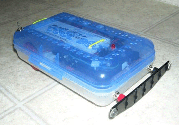
Construction Concepts and Goals
Construct a vehicle powered only by a standard 9 Volt battery that can avoid obstacles on the left and on the right. The vehicles will have two buttons mounted on the front (left and right). For example, if the vehicle hits the right wall, then the vehicle will stop, back up, turn left, and then continue the course.

Vehicle Parts
- Common Components
- Breadboard, wires, 10kW resistor, 1mF capacitor, 0.001mF capacitor, 9-Volt Battery
- Vehicle Chassis
- The chassis (pronounce as ‘cha-sE or ‘sha-sE) is the supporting frame of a structure. You can use metal sheets, a pencil box, a toy car, or anything that you like. [ Image ]
- 1 Caster
- A caster is a wheel mounted in a swivel frame that is commonly used for the support and movement of furniture and portable equipment. This is one of three wheels on the vehicle. [ Image ]
- 2 DC Motors with Wheels
- This motor offers 50 in·oz of torque, rotating 360 degrees every 1.6 seconds (38 rpm – just a hair slower than a servo), at 5V, drawing 600mA at stall (free running at 52mA). [ Image ] The motors have 90 degree output shafts and a 224:1 gearbox and were purchased from Solarbotics. (Search for “GM3 Motor”.)
- H-Bridge Chip
- An H-Bridge is a circuit that is constructed from transistors that allows you to change the direction of rotation of motors or stop the motors. [ Image ]
- The H-Bridge chip provided is a 754410 chip from Acroname that is great for controlling small motors at roughly 1A peak current.
- The 754410 is a single chip with 2 H-Bridges in it that can handle up to 1A per channel.
- The pin assignments can be found on the PDF Data Sheet provided.
- PIC Microcontroller: 16F84A or 16F819
- What is a microcontroller? A microcontroller as a single chip computer.
- The Programmable Integrated Circuit (PIC) Microcontrollers that we will use have 18 pins and are made by Microchip.
- The pin assignments can be found on the 16F84A PDF Data Sheet or the 16F819 PDF Data Sheet.
- As part of a PHY475 project at SFA, Randy Innerarity created Getting Started With The PIC Microcontroller.
- The assembly program written by Randy Innerarity for his SFA Rover will be used for each PIC Microcontroller. Teams can modify the program for their robot after the initial tests.
- Voltage Regulator 7805
- Voltage regulators are needed to reduce the 9-Volts provided by the battery to 5-Volts. [ Image ]
- These are Fairchild LM7805C regulators.
- The pin assignments can be found on the PDF Data Sheet provided.
- Two Buttons
- These buttons should be mounted on the front of the vehicle to detect obstacles to the left or right.
- These should be wired to the PIC Microcontroller.
Read More: THE SIMPLE ROVERBOT
