


Summary of Temperature controlled fan using PIC 16F877A
This project controls a DC motor speed based on external temperature using an LM35 sensor, a PIC16F877A microcontroller (with ADC and PWM), and an LCD. The LM35 output is read by the ADC, converted to temperature, displayed, and used to set PWM duty cycles across temperature ranges to vary fan speed automatically.Parts used in the Temperature controlled fan using PIC 16F877A:
- LM35 temperature sensor
- PIC16F877A microcontroller
- 16x2 LCD display (or compatible character LCD)
- DC motor (fan)
- Motor driver/output stage compatible with CCP1 PWM
- Power supply (Vcc 5V for MCU and peripherals)
- Crystal oscillator 20 MHz
- Supportive passive components (wires, connectors, decoupling capacitors)
You might have come across several applications where we need to control a specific device based on analog parameter. This Embedded system works in a similar concept where we are about to control the speed of a DC motor using based on the external temperature. The rise in temperature will result in increase in speed of the motor and vice versa. These type of Temperature controlled fan systems can generally be used to maintain temperature of a room or object automatically.
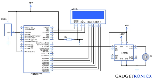
 DESIGN OF TEMPERATURE CONTROLLED FAN SYSTEM:
- The temperature is measured by means of a temperature sensor LM35.
- The output voltage of the sensor is fed to the A/D channel of the Microcontroller.
- Based on the sensed temperature the speed of the motor is controlled using PWM .
- Several temperature ranges was set in the code to vary the motor speed based on the level of temperature sensed.
- The speed of the motor is controlled by using PWM.
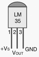
Lm 35 is used to sense the external temperature which is capable of sensing temperature ranges from -55 to 150 C. The output voltage is proportional to the temperature hence there is no need of trimmers to calibrate the reading. The output voltage of this sensor varies by 10mv per degree change in temperature.
 CALIBRATION:
We are using a 10 bit ADC and Vcc as Vref to the ADC module of the Controller. So in order to determine the step size we have to divide the Vref by our resolution that is 2^10 ( 1024 ).
Step Size = 5 / 1024 = 4.83mV
We obtain a change of 10mV with each rise or fall in temperature from the sensor. And value in the ADC register will alter by two steps with each degree change in the sensor since two increments of step size i.e 4.833mV * 2 = 9.96mV which is approximately equal to 10mV. So in order to obtain the original value we have to divide the contents in the ADC register by 2
CODE:
This code was built using CCS compiler for PIC Microcontrollers.
#include <16F877A.h>
#device ADC=10                              //Setting ADC bits
#FUSES NOWDT
#FUSES NOBROWNOUT
#FUSES NOLVP
#use delay(crystal=20000000)
#byte lcd=0x08
#byte TRIS_lcd=0x88
#bit rs=0x06.2
#bit en=0x06.3
#bit TRIS_rs=0x86.2
#bit TRIS_en=0x86.3
long int adc_value,real_value;
int i;
char value[4];
unsigned char text[]="Temperature:";
void display(unsigned char a, int b);
void motor();
void main()
{
  TRIS_lcd=TRIS_rs=TRIS_en=0;
  display(0x38,0);
  display(0x01,0);
  display(0x0c,0);
    for(i=0;i<=12;i++)
    {
     display(text[i],1);
    }
  setup_timer_2(T2_DIV_BY_16,255,1);    //Setting timers for PWM
  SETUP_ADC_PORTS(AN0);                   //Setting ADC PORTS
  SET_ADC_CHANNEL(0);                       //Selecting Channel
  SETUP_ADC(ADC_CLOCK_INTERNAL);
     while(TRUE)
      {
        delay_us(20);
        adc_value=READ_ADC();            //Reading ADC value
        delay_us(10);
        real_value=adc_value/2;           //Obtaining real value
        motor();
        sprintf(value,"%lu",real_value);  //Changing int to char
        display(0x8c,0);
          for(i=0;i<=3;i++)
           {
             display(value[i],1);
           }
      }
 }
void display(unsigned char a,int b)         //LCD sub routine
  {
    lcd=a;
    rs=b;
    en=1;
    delay_ms(10);
    en=0;
    delay_ms(10);
  }

void motor()
{
  if(real_value<10)
   {
   setup_ccp1(CCP_OFF);
   }
  if(real_value>10)
   {
     setup_ccp1(CCP_PWM);
      if(real_value>=10&&real_value<=29)
      {
        set_pwm1_duty((int16)204);         //20% duty cycle PWM
      }
      else if(real_value>=30&&real_value<=69)
     {
       set_pwm1_duty((int16)510);         //50% duty cycle PWM
      }
      else if(real_value>=70&&real_value<=99)
      {
         set_pwm1_duty((int16)715);      //70% duty cycle PWM
       }
      else if(real_value>=100&&real_value<=150)
       {
         set_pwm1_duty((int16)919);     //90% duty cycle PWM
       }
    }
 }
The above code uses built in functions in the CCS compiler to use the A/D and PWM feature in the Microcontroller. The received analog value is calibrated to display the temperature in the LCD. The “real_value” int value is converted to character using “sprintf” in order to display the temperature values.
The temperature ranges and duty cycle of the PWM is given using the subroutine “.motor”. So the microcontroller runs a check on the temperature every time and alters the speed of the motor based on it.
For more detail: Temperature controlled fan using PIC 16F877A
- What sensor is used to measure temperature?
The LM35 temperature sensor is used to sense external temperature. - How is the sensor output read by the controller?
The LM35 output voltage is fed to the ADC channel AN0 of the PIC16F877A and read using READ_ADC(). - How is the ADC calibrated to temperature?
With a 10-bit ADC and 5V Vref the step size is 5/1024 = 4.83mV; since LM35 gives 10mV per degree, the ADC value is divided by 2 to obtain the temperature in degrees. - How is motor speed controlled based on temperature?
Motor speed is controlled using PWM on CCP1 with duty cycles set for defined temperature ranges in the motor() subroutine. - What temperature ranges correspond to what PWM duty cycles?
The code sets: below 10°C PWM off; 10–29°C ~20% duty; 30–69°C ~50% duty; 70–99°C ~70% duty; 100–150°C ~90% duty. - How is the temperature displayed?
The ADC-derived real_value is converted to characters using sprintf and shown on the LCD. - Which compiler and built-in functions are used?
The CCS C compiler is used with built-in ADC and PWM functions like SETUP_ADC, READ_ADC, setup_ccp1, and set_pwm1_duty. - What reference voltage is used for the ADC?
Vcc (5V) is used as the Vref for the ADC.
Related projects
PIC16F877 Driving LCD in 4-Bit Mode using PIC16F877 with Proteus Simulation
Introduction This microcontroller project shows how a PIC16F877 can drive an LCD display using 4-bit mode inside a Proteus simulation.The project demonstrates...
Programmers & ICSP · PIC16F877AEPE PIC/LCD Demo using PIC16F877 with Proteus Simulation
IntroductionThe EPE PIC/LCD Demo is a classic microcontroller project that demonstrates how a PIC16F877 can fully control a PG12864F graphical LCD.Designed as...
Motors & Robotics · PIC16F877AEfficient Sun-Following Robot: A Solar Tracker with Microcontroller Control
Abstract The impending global challenge of dwindling non-renewable fuel resources underscores the urgency of transitioning towards renewable energy alternatives like solar power....
Sensors & TemperatureSpectrum Analyzer using TMS320F28023DA with Proteus Simulation
Introduction This project demonstrates a real-time audio spectrum analyzer using the TMS320F28023DA Piccolo microcontroller, simulated in Proteus VSM. The system captures an...
Sensors & TemperatureDHT22 Low Cost Humidity Sensor using PIC18F25K20 with Proteus Simulation
IntroductionThis microcontroller project demonstrates how to interface a DHT22 (RHT03) digital temperature and humidity sensor with a PIC18F25K20 using Proteus simulation.The project...
Sensors & TemperatureCrafting a Microcontroller-Based Temperature Monitoring System
Abstract As technological advancements progress, processes become increasingly intricate, demanding a corresponding expansion in the parameters necessary for efficient analysis. Data acquisition,...

Ibrar Ayyub
I am an experienced technical writer holding a Master's degree in computer science from BZU Multan, Pakistan University. With a background spanning various industries, particularly in home automation and engineering, I have honed my skills in crafting clear and concise content. Proficient in leveraging infographics and diagrams, I strive to simplify complex concepts for readers. My strength lies in thorough...