
Summary of STEPPER MOTOR DRIVER WITH PIC16F628A L297 L298 CIRCUIT
Summary (under 100 words): A teacher-requested stepper motor driver was designed using PIC16F628A as the controller with L297 and L298 driver ICs. The general-purpose driver supports 1.8° or 7.5° steppers, full and half-step modes, single-touch speed selection, and step-by-step movement. PIC16F628A provides PWM (RB3) as L297 clock and controls Enable, CW/CCW, and HALF/FULL signals. A 2x8 LCD displays status. The project was tested with a 6-wire unipolar motor and operated the motor in bipolar mode by tying commons, noting higher current at low speeds.
Parts used in the Stepper Motor Driver with PIC16F628A L297 L298 Circuit:
- PIC16F628A microcontroller
- L297 stepper motor controller IC
- L298 dual H-bridge driver IC
- 2x8 LCD display
- Stepper motor (1.8° or 7.5°, tested with 6-wire unipolar)
- Power supply for motor and logic
- Pushbuttons for speed selection and step control
- Clock/PWM connection (PIC RB3 pin)
- Wiring, connectors, and PCB or protoboard
Hello, friends. I have designed at the request of a teacher stepper motor driver circuit I want to share with you. System is going to start actually quite a few. But barely was able... Electronics Projects, Stepper Motor Driver with PIC16F628A L297 L298 Circuit “microchip projects, microcontroller projects, motor control circuit, motor driver circuit, pic16f628 projects, pwm circuits, “
Hello, friends. I have designed at the request of a teacher stepper motor driver circuit I want to share with you. System is going to start actually quite a few. But barely was able to finish due to the intensity of work.
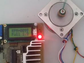
I made the drive has been designed as general. So it does not serve any particular purpose. In short, was to observe the operation of stepper motors can say. I have done with the drive stepper motor with a step angle of 1.8 or 7.5 can be used. Engine Full and Half-driving mode can take. In addition to the previously set speed can remove one touch. Or the engine can move step by step.
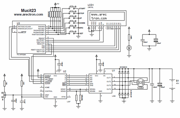
As the title suggests, L297 and L298 at the binary driver I used. Through integrating these two stepper motors can do many operations on /
As usual as the main control PIC16F628 and LCD 2X8 in the process I use to view. L297 clock frequency of PIC16F628 ‘s RB3 pin PWM hardware module that promise. Also L297’N Enable, CW-CCW and HALF / FULL pinlerini I’m checking with the 16F628. I like the hardware in general.


In the video the engine has an engine 6-ended unipolar. But after applying power to the common end of the engine at low revs me for taking too much current as bipolar çalıştırdıdm engine. So the drive end only depend on the phase of the motor.
Source: STEPPER MOTOR DRIVER WITH PIC16F628A L297 L298 CIRCUIT L297 L298 Stepper Motor Driver with PIC16F628A files: stepper-motor-driver-with-pic16f628a-l297-l298-circuit.rar
- What microcontroller is used in the project?
The PIC16F628A microcontroller is used as the main controller. - Which driver ICs are used to drive the stepper motor?
The project uses L297 as the controller IC and L298 as the H-bridge driver IC. - What step angles of motors can be used?
The driver supports stepper motors with 1.8° or 7.5° step angles. - Does the circuit support half and full step modes?
Yes, the circuit can operate in both full-step and half-step driving modes. - How is the L297 clock provided?
The L297 clock is provided by the PIC16F628A PWM hardware on RB3. - Can the user change speed easily?
Yes, the previously set speed can be selected with one touch according to the article. - Is there a display for status information?
Yes, a 2x8 LCD is used to view status during operation. - Can the motor be moved step by step?
Yes, the engine can be moved step by step as described. - What happened when using a 6-wire unipolar motor in testing?
The 6-ended unipolar motor was run in bipolar mode by tying the common, and it drew much current at low speeds.
