
Summary of A combined MSF/DCF atomic clock receiver
This project combines two radio-clock receiver modules (one modified from DCF to MSF by replacing a 77.5 kHz crystal with a 60 kHz crystal) to receive and display both MSF and DCF time signals. The supply is 5V with a 3.3V zener for the modules; outputs and LEDs can be inverted via links. Two 7400 NANDs per group act as NOT gates. A BASIC graphics program plots MSF (yellow) and DCF (green) outputs, highlighting minute markers and timing differences. PCB, circuit diagram, and program files are provided in a zip.
Parts used in the Combined MSF DCF atomic clock receiver:
- Two radio clock receiver modules (originally DCF)
- 77.5 kHz crystal (original, replaced)
- 60 kHz crystal (used to convert one module to MSF)
- 5V supply source
- 3.3V zener diode (supply for receiver modules)
- Links/jumpers (four links for output and LED inversion)
- 7400 NAND ICs (used as NOT gates, two NANDs per NOT group)
- Ferrite rod antennas (for the two modules)
- LEDs (indicator LEDs for module outputs)
- PCB (printed circuit board for the circuit layout)
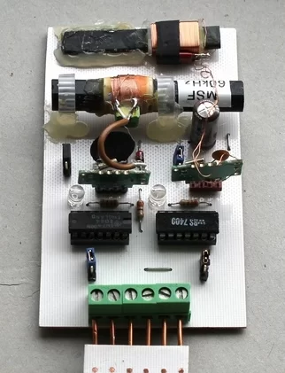
For this to work you must obviously live in an area that can receive both signals. My circuit is based on two modules taken from two radio clocks bought at Lidl’s supermarket. Originally both were for the DCF clock but by substituting the original 77.5kHz crystal with a 60kHz crystal, one of the modules was converted to MSF.
Notice that both antennas are lined up in my photograph. This is because Anthorn and Mainflingen – as seen from Limavady – are roughly in the same direction. The alignment of the ferrite rods obviously has to be adapted to your location.
Circuit description
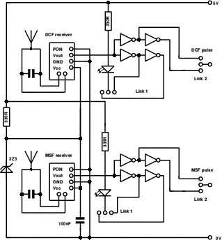
The circuit is based on the single clock projects found elsewhere on this site. The supply for the two actual receiver modules makes use of a 3.3V zener diode. Supply voltage is 5V. The four links allow both the output signals and the LEDs to be inverted by moving the link. Each group of four NOT gates – on the pcb – consists of two 7400 NAND gates wired as Not gates.
I found that the circuit worked extremely well and reception is near perfect under most conditions.
The program
I have written a simple little single tasking graphics program which plots the output of both clocks one over the other. The MSF clock is yellow, the DCF clock is green. On the right is a small section of the output.
Not much can be learned. The most interesting bits are the beginning of minute markers. This is a half second ON for the MSF clock and a full second OFF for the DCF clock. Notice also the double pulse in first DCF second indicating a 100ms difference between atomic time and GMT. This used to be 400ms not all that long ago.
I have highlighted the interesting bits. Anything you see in red was not produced by my program but inserted via !Draw.
Here is a link to a zip file containing the draw file of the pcb layout, the circuit diagram and the BASIC V program below.
Version 2 of the program allows you to plot continuously or screen after screen. You can also change the time base.
For more detail: A combined MSF DCF atomic clock receiver
- Can the DCF module be converted to receive MSF?
Yes. In the project one module was converted by substituting the original 77.5 kHz crystal with a 60 kHz crystal. - What supply voltage does the circuit use?
The supply voltage is 5V, with a 3.3V zener diode used for the receiver module supply. - How are the outputs and LEDs inverted?
By moving the four links on the PCB which allow both the output signals and the LEDs to be inverted. - Which ICs are used as NOT gates?
Each group of four NOT gates on the PCB consists of two 7400 NAND gates wired as Not gates. - What does the BASIC graphics program display?
It plots the output of both clocks one over the other: MSF in yellow and DCF in green, with a small section of the output shown on the right. - What are the distinguishing minute markers for MSF and DCF?
The MSF minute marker is a half second ON, and the DCF minute marker is a full second OFF. - Does the project require being within range of both signals?
Yes. To work you must live in an area that can receive both signals. - Why are the antennas aligned in the photograph?
Because Anthorn and Mainflingen are roughly in the same direction from the author's location, so the ferrite rods were aligned accordingly. - What additional files are provided for the project?
A zip file contains the pcb draw file, the circuit diagram, and the BASIC V program.

