Summary of Stepper Motor Controller using PIC16C84
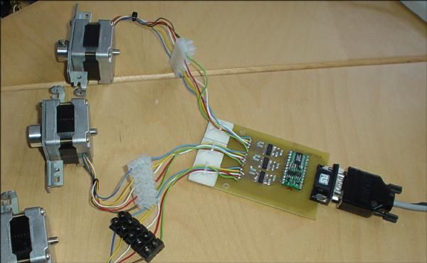
This article details building a stepper motor controller using a PIC16C84 microcontroller. It explains identifying motor coils via resistance measurement and driving them using transistors, driver ICs, or specialized chips. The guide includes circuit design considerations for back-EMF protection and provides downloadable C source code and hex files for forward rotation and 180-degree sweeping operations.
Parts used in the Stepper Motor Controller:
- Stepper motor (salvaged or from surplus store)
- PIC16C84 microcontroller
- 2N2222 transistor (or TIP29 for larger motors)
- Protection diodes
- Resistors
- Meter (for measuring resistance)
- Circuit board
- Coil schematic
- stepper.c source file
- stepper.hex file
- stepper2.c source file
- stepper2.hex file
For another project I started I needed to control the motion of a stepper motor. A stepper motor is used when precision control of movement is needed. With each movement of the motor, the drive shaft steps a precise amount of distance (usually a few degrees with each turn). You can often salavage steppers from old printers or disk drive. I found mine at an electronics surplus store.
The key to driving a steper is realising how the motor is constructed. A diagram shows the representation of a 4 coil motor, so named because 4 coils are used to cause the revolution of the drive shaft. Each coil mut be energized in the correct order for the motor to spin.
Mapping the coils to your motor
Given a motor you have just scavanged, how do you determine which wire corresponds to which coil? Simple: use a meter to measure the resistance between pairs of wires. Each coil will exhibit a low resistance of a few hundred ohms. Choose a pair of wires and measure the resistance. Then choose another pair and again measure the resistance. If the resistance across the first pair is double that of the second pair, then the first pair corresponds to the wire pair (1,3) or (4,6). The second pair of wires will correspond to one of (1,2), (2,4), (4,5) or (5,6). Repeat this until you have mapped each wire on your motor to one of the coils.
Driving a Stepper Motor
To cause the steper to rotate, we have to send a pulse to each coil in turn. The PIC does not have sufficient drive capability on its output to drive each coil, so there are a number of ways to drive a stepper:
- Use a transistor to drive each coil. I used this approach first to test my ideas. It was a little awkward to wire up the circuit – board space becomes an issue with 4 transistors, resistors and diodes per coil. Also, it requires 4 pins on the PIC to drive the motor. You can only drive 3 motors from one PIC (using all of PORTA and PORTB pins).
- Use a driver array packaged in a IC. This is a simple solution that works nicely. Don’t forget to wire in the protection diodes!
- Use a specialized stepper motor driver chip. I haven’t tried this yet, but it would save on board space, and pin usage.
Driving a coil using a Transistor
Here is a simple schematic of how to drive a single coil using a 2N2222 transistor. I choose this transistor because it was what I had lying on my desk at the time! You can easily substitute your own favourite transistor. Bigger motors will require a bigger transistor, e.g. a TIP29.
Remember: the diode is needed when the coil is turned off. A large back-emf current is generated by the collapsing magnetic flux field in the coil. This current could damage the transistor, so the diode provides it a place to go. The current is generated in the opposite direction from that needed to drive the coil, hence the diode is wired in “backwards”.
This schematic shows how to wire one output of the PIC to the stepper motor.
Source Code
The following files are available for download:
- Coil schematic
- Schematic for connecting the PIC to a coil.
- stepper.c C source to run the motor forwards.
- stepper.hex hex file for the stepper.c code. Can be downloaded directly to PIC.
- stepper2.c C source to sweep the motor back and forth by 180 degrees.
- stepper2.hex hex file for the stepper2.c code. Can be downloaded directly to PIC.
For more detail: Stepper Motor Controller using PIC16C84
- How do you determine which wire corresponds to which coil on a salvaged motor?
Use a meter to measure resistance between pairs of wires; coils exhibit low resistance of a few hundred ohms, and comparing ratios helps map the wires. - Why is a diode needed when driving a coil with a transistor?
The diode protects the transistor by providing a path for the large back-emf current generated when the coil is turned off. - What are the three methods mentioned for driving a stepper motor?
The article lists using individual transistors, a driver array packaged in an IC, or a specialized stepper motor driver chip. - Can a single PIC drive multiple motors using the transistor method?
You can only drive 3 motors from one PIC using all PORTA and PORTB pins because each coil requires a dedicated pin. - What should you use if your motor is bigger than the standard size?
Bigger motors will require a bigger transistor, such as a TIP29, instead of the 2N2222. - Does the PIC have sufficient drive capability to drive each coil directly?
No, the PIC does not have sufficient drive capability on its output to drive each coil without external components. - What is the purpose of the stepper2.c source file?
The stepper2.c file contains the C source code to sweep the motor back and forth by 180 degrees. - Where can you typically find stepper motors for this project?
You can often salvage steppers from old printers or disk drives, or find them at an electronics surplus store.