


Summary of Stand-alone Heart Rate Meter
This article outlines building a standalone heart rate meter using the Easy Pulse mikro sensor, mikroElektronika's Clicker 2 for PIC18FJ board, and an OLED W click board. The system reads PPG waveforms via a PIC18F87J50 microcontroller to calculate beats per minute by detecting peaks in the signal.Parts used in Stand-alone Heart Rate Meter:
- Easy Pulse mikro sensor
- Clicker 2 for PIC18FJ board
- OLED W click board
- PIC18F87J50 microcontroller
- mikroBus sockets
- USB bootloader
- Source code (mikroC Pro for PIC)
- HEX file
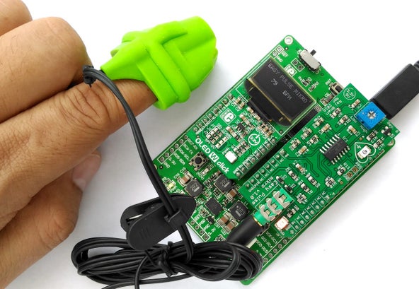
Step 1: Setup, Firmware, and Output
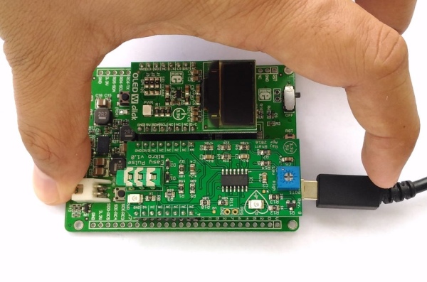
The clicker 2 development board features Microchip’s powerful 8-bit PIC18F87J50 microcontroller, preprogrammed with an USB bootloader, and two mikroBus sockets to receive add-on boards. For this demo project, the OLED W click board is inserted into socket 1 and Easy Pulse mikro to socket 2, as shown below.
The firmware for this project can be downloaded from the following link. It contains both the source code (written in mikroC Pro for PIC) and HEX file.
Clicker2_PulseMeter_EasyPulse_Firmware
The flow diagram shown here describes how the pulse rate is computed from the PPG waveform. The PIC microcontroller reads in 600 analog samples of the PPG waveform at 5 millisecond sampling interval and finds three consecutive peaks in the PPG waveform. The pulse rate can then be computed from the time interval between any two successive peaks.
Source: Stand-alone Heart Rate Meter
Quick Solutions to Questions related to Stand-alone Heart Rate Meter:
-
What components are needed to build this project?
You need an Easy Pulse mikro sensor, a Clicker 2 for PIC18FJ board, and an OLED W click board. -
How does the system display the heart beat rate?
The OLED W click board displays the heart beat rate in beats per minute (BPM). -
Which microcontroller is used in the Clicker 2 board?
The board features Microchip's powerful 8-bit PIC18F87J50 microcontroller. -
Where should the boards be inserted on the development kit?
The OLED W click board is inserted into socket 1 and the Easy Pulse mikro into socket 2. -
How many analog samples does the microcontroller read?
The PIC microcontroller reads in 600 analog samples of the PPG waveform. -
At what interval are the samples taken?
The samples are taken at a 5 millisecond sampling interval. -
How is the pulse rate computed from the waveform?
The system finds three consecutive peaks in the PPG waveform and computes the rate from the time interval between successive peaks. -
Can I download the firmware for this project?
Yes, the firmware containing source code and HEX files can be downloaded from the provided link.
Related projects
Determine capacitance by measuring the charging time using PIC16F688
When TEST botton is pressed, RA3 pin is set to "1". R2 and R3 are divide the voltage to 1/2 Vra3 which...
Meters & Test InstrumentsFrequency Meter Using Microcontroller
This tutorial simply states how to calculate frequency of a pulse source using a microcontroller. Story https://youtu.be/NAoj-HLRIro This tutorial simply states how...
Meters & Test Instruments · PIC16F84ADigital thermometer with PIC16F84 circuit
This electronic project is a very simple thermometer that is based on the PIC16F84A microcontroller, designed by Microchip. Why to use a...
Meters & Test InstrumentsProjects on Speed Checker To Detect Rash Driving On Highways
While driving on highways, drivers should not exceed the maximum speed limit permitted for their vehicle. However, accidents keep on occurring due...
Meters & Test InstrumentsDigital Ammeter circuit using pic microcontroller
In this project we have a tendency to design a circuit to build an electronic voltmeter while not making use of any...
Meters & Test InstrumentsTampered Energy Meter Monitoring Conveyed to Control Room by GSM with User Programmable Number Features
The main concept of this project is to reduce the power theft by using an integrated energy meter such that whenever an...

Muhammad Bilal
I am a highly skilled and motivated individual with a Master's degree in Computer Science. I have extensive experience in technical writing and a deep understanding of SEO practices.