Summary of SMS Based Device Control using GSM Modem
This article introduces a GSM-based home appliance control system using a PIC16F877A microcontroller. The system receives SMS commands from anywhere globally to switch devices on or off via relays connected to PORTD. An LCD displays system status, while the GSM module handles text mode communication and message parsing to trigger specific actions based on "ON" or "OFF" keywords in the received text.
Parts used in the GSM Based Device Monitoring and Control System:
- PIC16F877A
- GSM Module
- LCD (2X16)
- Transistor (BC548)
- Resistor (1K, 10K, 470×8, 10K(POT))
- Crystal (4MHz)
- Capacitor (22pfx2, 10uF)
- Push button
- LED x8
It has been a while since we published electronic engineering projects here due to the busy schedule we had in the past weeks, and this time we’re up with another interesting project. Before going through the details of this one, you may as well check our latest electronics projects for engineering students.
GSM based device monitoring and control system are becoming popular these days. Here I am introducing a system that will make home appliances controlling using mobile phone possible from anywhere in the world. It’s a PIC microcontroller based system which connects with GSM module to receive SMS for the smart home control. The message is then processed by the microcontroller and output is given through PORTD of PIC microcontroller. All the devices are connected on PORTD through relay.
Also See: DTMF cell phone controlled home appliances
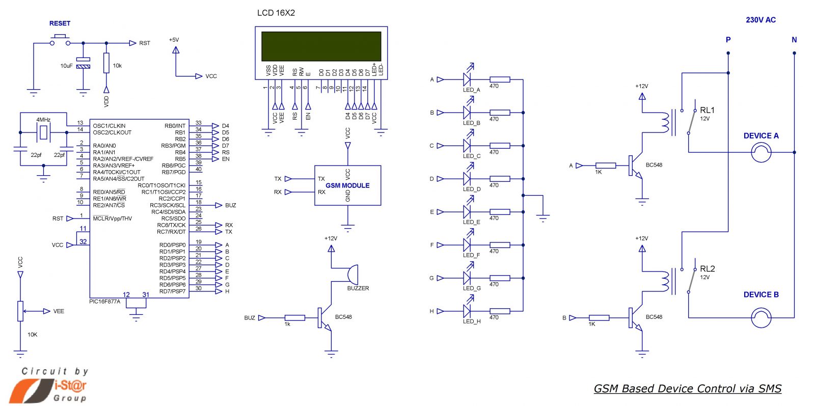
Home appliances controlling using mobile phone circuit
Components Required
- PIC16F877A
- GSM Module
- LCD (2X16)
- Transistor (BC548)
- Resistor (1K, 10K, 470×8, 10K(POT))
- Crystal (4MHz)
- Capacitor (22pfx2, 10uF)
- Push button
- LED x8
Working of the circuit
- Serial pin of PIC Microchip (RX and TX) is connected to the GSM module to control it via AT commands so as to receive SMS and set the mode.
- When the system is ON, PIC will initialize the GSM module and wait to receive SMS.
- 2×16 LCD display is connected to PORTB of PIC, it will display the status of the system (i.e. it will display what the system is doing).
- Initially GSM module is switched to Text mode by sending the AT command “AT+CMGF=1”. Here “1” indicates text mode and “0” is used to indicate PDU mode.
- After this setting, PIC will display that it’s waiting for SMS and will wait to receive SMS.
- The reception of SMS is detected by checking the received character; it will send all information about the SMS which starts with”+CMT”. Message text content will start after sending”\n” and ending with”\n”. This is the logic I have used here to receive SMS.
- I have used an infinite loop which continuously checks if a ‘+’ is received, followed by ‘C’, ‘M’ and ‘T’.
- Then the system understands that a massage is going to be received and waits for a $ (dollar sign), if done it will store the entire message on a buffer of size 33 named as INFO. It’s again split and stored on two separate buffers for further processing.
- After this, PIC will display “SMS IS RECEIVED”on first row and “DEVICE SWITCHING” in the second row. It also enables a buzzer for 2 seconds as an audio indication of SMS reception.
- A variable “count” is initiated as “1” and the received SMS information is now on the buffer named line1, the letter on line1[0] is skipped and takes line1[1] because the message for ON and OFF is sent as “$ON ABCDEFGH$” and “$OFF ABCDEFGH$”; in both cases Zeroth letter (“O”) is common, so I skipped it.

- The fist letter indicates that the message is for ON or OFF. Here I have used two ‘for’ loops, one to set PORTD bits (ON the devices) and other one to reset the PORTD bits(OFF the devices).
- ON and OFF detection is done by checking the first character (line1[1]) of the message, “N” for ON and “F” for OFF.
- After detecting the message it will enter into the corresponding loop of SET or RESET pins. Then the relays connected to these pins activate or deactivate.
- For demonstration purposes I have used LEDs and in the circuit diagram I have mentioned how to connect relay in order to connect high current devices.
- To switch ON the devices, you may send SMS as “$ON ABC$” to ON A, B and C; “$OFF B$” to switch OFF B.
- We have designed this system to switch 8 individual devices and you can improve it through simple modification of the program and hardware.
For more detail: SMS Based Device Control using GSM Modem
- How does the system receive commands?
The system receives SMS commands via a GSM module connected to the serial pins of the PIC microcontroller. - What command sets the GSM module to text mode?
The AT command AT+CMGF=1 is sent to switch the GSM module to text mode. - How does the microcontroller detect an incoming SMS?
The system checks for a '+' character followed by 'C', 'M', and 'T' to detect an incoming message. - What format must the SMS follow to control devices?
The message must be formatted as $ON ABCDEFGH$ or $OFF ABCDEFGH$ where letters represent device addresses. - Which port connects the relays to the microcontroller?
All devices are connected to PORTD of the PIC microcontroller through relays. - What display component shows the system status?
A 2x16 LCD connected to PORTB displays the status of the system. - Can this system control more than eight devices?
The current design switches 8 individual devices, but it can be improved with simple program and hardware modifications. - How does the system indicate an SMS was received?
The system displays SMS IS RECEIVED on the LCD and enables a buzzer for 2 seconds. - How are ON and OFF states determined?
The system checks the first character after the dollar sign; N indicates ON and F indicates OFF. - What happens if the user sends $OFF B$?
The system will switch OFF device B by resetting the corresponding pin on PORTD.