
Servo motors are widely used in robotics and industries for motion control. They can be controlled by PWM signals where the required angle of rotation can be located by a particular PWM signal. So In this article we’ll see in detail on PWM servo control and how servo motor control using pic16f877a is possible. Servo motors have an output shaft which is connected to an arm and the mechanical connections are attached with this arm, which can rotate a maximum of 180 degree. It has three connection wires: V positive, V negative and control signal. Signal is normally connected with microcontrollers to feed PWM signal as required. The position of servo arm is determined by PWM signal: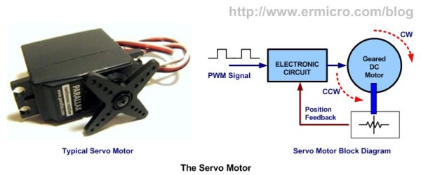
- 1500µs for servo neutral position.
- If the signal is less than 1500µs then the arm moves back to a particular angle (anti clockwise).
- If the signal value is greater than 1500µs then the arm move clock wise to a particular angle depending on the signal value.
Read: How to generate PWM using PIC microcontroller?
PWM DC motor speed controller using PIC16F877A
PWM of 1000µS will move the arm to zero position which is the minimum position and 2000µS will move the arm to maximum. Servo motor has inbuilt control circuit to convert the PWM signal to the position value, it has a movable potentiometer which is used to locate the position by balancing mechanism.
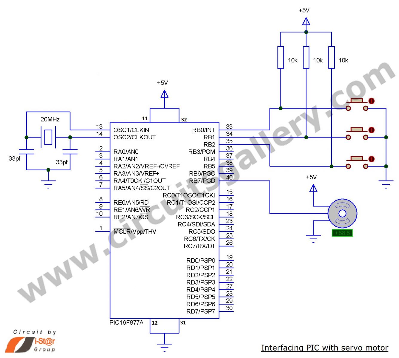
Servo motor control circuit
Components Required
- PIC16F877A
- Crystal 20MHz
- Capacitor (33pf x 2)
- Resistor (10K x 3)
- Servo motor
- Push buttons x 3
Working
- Here I use three switches to rotate the arm to -90 degree (minimum position), zero degree and +90 degree.
- Arm rotates these three positions by pressing the switches.
- The application of this in a robot is to turn the front wheel by pressing the buttons on the remote, but here rotation is 90 degree so you have to minimize this by changing the PWM signal.

- Here we have used the mikroC compiler.
- Port B is used to connect servo motor and controlling switch, the controlling switches are connected to +5V through a 10K (called pull up) resistor.
- The control signal of a servo motor is connected to 7th bit of port and switches are connected to 0th, 1st and 2nd pin of PORTB.
- Three sub functions are used to move the arm left, straight and right for -90, 0 and +90 rotation.
- In main function, there is an infinite loop which continuously checks the 0, 1 and 2nd pins of PORTB.
- If any switch gets a negative signal when pressing the button then the program control is changed to the sub function for the particular switch and it return back to the infinite loop.
For more detail: Servo Motor Control using Microcontroller PIC16F877A
About The Author
Ibrar Ayyub
I am an experienced technical writer holding a Master's degree in computer science from BZU Multan, Pakistan University. With a background spanning various industries, particularly in home automation and engineering, I have honed my skills in crafting clear and concise content. Proficient in leveraging infographics and diagrams, I strive to simplify complex concepts for readers. My strength lies in thorough research and presenting information in a structured and logical format.
Follow Us:LinkedinTwitter