Summary of Electronic Die using PIC16F84 microcontroller
This article details the construction of a miniature electronic die using PIC microcontrollers. The author initially developed a prototype with a PIC16F84 as a learning exercise, later optimizing the design for a smaller PIC12F675 to create a compact, battery-efficient device. The project includes source code, hex files, and PCB artwork, utilizing components like LEDs, a push-button switch, and a CR2032 battery. The final version fits on a small strip board or custom PCB, achieving a size comparable to a 50 pence piece while consuming minimal power in sleep mode.
Parts used in the Electronic Die:
- PIC16F84 microcontroller
- PIC12F675 microcontroller
- Microchip MPLAB IDE V5.70
- LEDs (high efficiency required)
- Push button switch (SW1)
- CR2032 3V lithium battery
- Battery holder
- 9 pin 270R SIL resistor pack (or 8 pin)
- Strip board or custom PCB
- 12F675 Programmer PCB
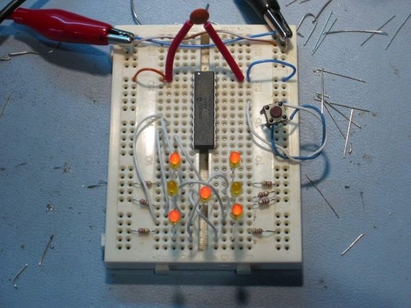
Built using a PIC16F84, about 4 hours worth of code and a few bits on a breadboard. This was the first time I’ve worked with PIC’s so it was a learning exercise. I started with the ‘Hello World’ microcontroller equivalent i.e. Blinking LED, then tried the ‘Knight Rider’ sequencing LEDs, and then hacked this together. The code is written and assembled using the Microchip MPLAP IDE V5.70. I only did this as an exercise to familiarise myself with PIC assembler, but having got it working I decided I wanted it smaller and as I had just acquired some 12F675s I took the original 16F84 code and developed it further to work with the 12F675.
For those of you who don’t know, and to save you the trouble of sending me an email to point out your ignorance, dice is the plural of die see here.
LED die using PIC16F84 Die on bread board, and Programmer (the neat PCB to left) with Die breadboard foreground and my circa 1985 Computer PSU, modified to get supply for PIC programmer. The assembler code was written to work, not as an example I’m afraid, so no apologies for the quality. I haven’t done any further work with this since I decided the 8pin PIC12F675 was better suited for building a miniature die. You should also note that if you do build a die using the 16F84 code below it is flawed in that it throws with unequal probability.
- Source code (the 12F675 die source below is better documented and developed)
- Hexfile ready to program (right-click Save As)
- Circuit schematic
LED die using PIC12F675. Starting with the 16F84 code above I’ve modified and developed it further to run on an 8 pin 12F675 device. This device has an internal 4Mhz oscillator so it needs no external support components and results in this minimum part die. I got this PIC for £0.99p so I reckon you can build the whole thing for about £2.50. You don’t need a power switch since the PIC ‘sleeps’ between throws and uses just a few micro Amps in this state.
- Source code.
- Hex file ready to program (right-click Save As)
- Circuit schematic PNG , PDF
- PCB Artwork
Three months after I built these prototypes I finally got round to producing a PCB for the die. The artwork is available from the link below. Rather than using discrete resistors the PCB layout uses a 9 pin 270R SIL resistor pack (Actually only needs an 8 pin one, the PCB will accommodate either). When you fit the button cell battery holder, check to make sure it doesn’t short out any of the component leads behind it. You do need to use high efficiency LEDs with this otherwise they won’t be bright enough and if you increase the current by reducing the value of the resistor pack it will impact on battery life.
- PCB Overlay (pdf)
- PCB Layout (pdf)
The artwork above is the second revision of the PCB. The photo’s below show the die built on the first PCB version I did. This is pretty much identical to the second, I just manually tweaked some of the auto routed tracks and removed the connector for an external power connector.
Top image. Bottom image
- Operation
When the die first starts after power is applied it initialise the device and then goes to sleep until the SW1 ‘roll’ button is pressed. While the button is pressed the display is blank. On releasing the button the LEDs ‘spin’ for about 5 seconds. The ‘throw’ is then display for 20 seconds at the end of which the LEDs fade down and turn off over about 2 seconds. If the throw button is pressed during this time, the die throws again, otherwise after 22 seconds the die goes back to sleep. I’ve built four of these die, all running from CR2032 3V lithium cells. One of these which I keep on my desk is still working on the original battery after 15 months.
Here’s an Ultra Small Die that I’ve built using a 12F675. This would be ideal for a surface mount design but I haven’t gone that far with it. This is built on an tiny bit of strip board, with some careful assembly and creative use of a baked bean can I’ve got down to the size of a 50 pence piece.
- Front View,
- Rear View before attaching battery holder
- Completed with battery holder attached (made from lid of Baked Bean can) attached.
- Third one with SM battery holder, PIC soldered directly into circuit.
For more detail: Electronic Die using PIC16F84 microcontroller
- Why did the author switch from PIC16F84 to PIC12F675?
The PIC12F675 is better suited for building a miniature die because it has an internal 4MHz oscillator requiring no external support components. - Does the original PIC16F84 code produce fair dice rolls?
No, the code for the 16F84 is flawed and throws with unequal probability. - How much does it cost to build the entire die?
You can build the whole thing for about £2.50 since the PIC chip costs around £0.99. - Is a power switch necessary for this project?
No, a power switch is not needed because the PIC sleeps between throws and uses only a few micro Amps in that state. - What happens when the roll button is pressed?
The display blanks while pressed, then the LEDs spin for about 5 seconds upon release before showing the throw. - How long does the result stay visible on the die?
The throw is displayed for 20 seconds before the LEDs fade down and turn off over about 2 seconds. - Can you press the button again while the result is displayed?
Yes, if the throw button is pressed during the display time, the die will throw again immediately. - What type of battery was used for the prototypes?
The prototypes were built running from CR2032 3V lithium cells. - How long can one battery last in operation?
One unit kept on a desk remained working on its original battery after 15 months. - What is the smallest size achieved for the die?
A version built on strip board with creative assembly reached the size of a 50 pence piece.