Summary of SECURITY ALARM CIRCUIT WITH PIC16F877 LCD
This project details a security alarm system built around the PIC16F877 microcontroller, featuring a 2×16 LCD for status display and a keypad for user interaction. The circuit supports eight TRIAC outputs capable of controlling various devices via relays. Comprehensive resources including circuit diagrams, PCB layouts, assembly source code, hex files, and installation guides are provided to facilitate implementation and customization.
Parts used in the Security Alarm with PIC16F877:
- PIC16F877 microcontroller
- 2×16 LCD indicator
- Keypad
- TRIAC outputs (8 pieces)
- Relay modules
- Circuit board components
Security Alarm project 16f877 microcontroller Board 2×16 lcd indicator alarm circuit connected to the keypad on the necessary adjustments can be made. Circuit diagram pcb drawings, asm source, hex codes, alarm installation, lcd menu... Electronics Projects, Security Alarm Circuit with PIC16F877 LCD “microchip projects, microcontroller projects, pic16f877 projects, “
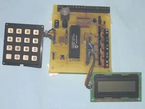
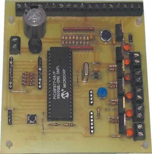
Security Alarm project 16f877 microcontroller Board 2×16 lcd indicator alarm circuit connected to the keypad on the necessary adjustments can be made. Circuit diagram pcb drawings, asm source, hex codes, alarm installation, lcd menu information (in English). Alarm circuit 8 pieces TRIAC output connect this outputs relay can be controlled by a variety of devices such as elements.
Source: SECURITY ALARM CIRCUIT WITH PIC16F877 LCD Alternative link: security-alarm-circuit-with-pic16f877-lcd.RAR
- What microcontroller is used in this security alarm project?
The project uses the PIC16F877 microcontroller. - How many TRIAC outputs does the alarm circuit support?
The circuit includes 8 pieces of TRIAC output. - Can different devices be controlled by this alarm system?
Yes, the outputs can control a variety of devices such as elements through relays. - What type of display is connected to the circuit?
A 2×16 LCD indicator is connected to the circuit. - Is there a keypad included for adjustments?
Yes, the alarm circuit is connected to a keypad where necessary adjustments can be made. - Does the article provide source code for the project?
Yes, ASM source and hex codes are available. - Are PCB drawings provided for this project?
Yes, circuit diagram and PCB drawings are included. - Is the LCD menu information available in English?
Yes, the LCD menu information is provided in English.