Summary of RGB LED DRIVER CIRCUIT PIC12F629 PWM
Summary: An RGB LED driver uses a PIC12F629/675/683 to PWM-drive STP36NF06 MOSFETs, fading between colors so all channels reach targets simultaneously. It uses the PIC internal 4 MHz oscillator with OSCCAL read from program memory. Assembly source, HEX, schematics, PCB and sequence data files are provided; correct SequenceData.inc formatting and device selection in MPLAB are required to avoid assembly/runtime errors.
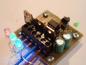
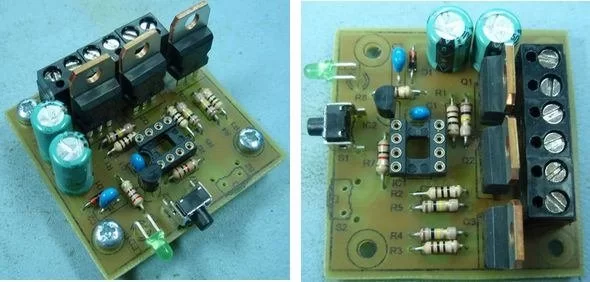
Parts used in the RGB LED Driver Circuit:
- PIC12F629 microcontroller (or PIC12F675 / PIC12F683 as alternative)
- STP36NF06 N-channel MOSFETs (three for R, G, B outputs)
- RGB LED or three separate high-power LEDs (Red, Green, Blue)
- Resistors for MOSFET gates and LED current limiting
- Power supply (appropriate voltage/current for LEDs and MOSFETs)
- Decoupling capacitors for PIC power rails
- PCB board and connectors
- Programmer compatible with PIC12F6x series (for MPLAB HEX upload)
- Optional: header or switch for configuration/sequence data programming
RGB LED driver circuit can be controlled with PIC12F629 pic12f675 As an alternative, can be used PIC12F683 PIC GP0, GP1, GP2 STP36NF06 in output MOSFETs are driven by PWM technique internal oscillator of the...Electronics Projects, RGB LED Driver Circuit PIC12F629 PWM “led projects, microchip projects, microcontroller projects, pwm circuits, “
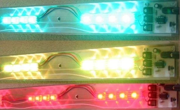
Code to fade between colours is completely rewritten to use variable rate of change so that all three LEDs arrive at their new levels simultaneously. This code will run on 12F629 / 12F675 and 12F683. Select the desired processor from the Configure – Select Device menu option in MPLAB IDE, then use the Project – Quickbuild option to create the HEX output file.
Look for errors during assembly. In particular errors in the SequenceData.inc file that indicate either a missing comma in the data, or more data than the chosen PIC has available program memory. Be carefull to enter the data in the SequenceData.inc file correctly. The program is only smart enough to work out where your sequences start and finish if you enter it in the correct format. Errors in the data may cause the code to crash.
All timings are based on the internal 4Mhz PIC oscillator. The OSCCAL value is read from program memory at 0x3FF and written to the OSCAL register. This value must be present and correct.
Source: RGB LED DRIVER CIRCUIT PIC12F629 PWM alternative link: rgb-led-driver-circuit-pic12f629-pwm.rar alternative link2
- Can I use other PICs besides PIC12F629?
Yes, the code also runs on PIC12F675 and PIC12F683 as stated in the article. - How are the MOSFETs driven?
The MOSFETs (STP36NF06) are driven by PWM outputs from the PIC. - Does the project use an external crystal?
No, the internal 4 MHz oscillator of the PIC is used instead of an external crystal. - What must I check in MPLAB before building the HEX file?
Select the desired processor from Configure – Select Device and use Project – Quickbuild to create the HEX output file. - Where is the OSCCAL value read from?
The OSCCAL value is read from program memory at address 0x3FF and written to the OSCAL register. - What common assembly errors should I look for?
Look for errors in the SequenceData.inc file such as missing commas or too much data for the chosen PIC program memory. - How does the color fading algorithm improve transitions?
The fade code uses variable rate of change so all three LEDs arrive at their new levels simultaneously. - What happens if SequenceData.inc is formatted incorrectly?
Incorrect formatting may prevent the program from determining sequence boundaries and can cause the code to crash.