Summary of RF Thermostat
This article details the first part of a DIY RF Thermostat project designed to control an infrared heating panel. Built around a PIC16F1823 microcontroller, the device measures room temperature with a DS18B20 sensor and displays data on 7-segment LEDs. It uses a custom 433 MHz one-way RF protocol to send "on" or "off" commands to a relay every two minutes, solving reliability issues found in commercial systems. The software is written in JAL without external libraries, allowing for precise temperature control and manual programming via push buttons.
Parts used in the RF Thermostat:
- Breadboard
- PIC microcontroller 16F1823
- 74HC595 Shift Register
- DS18B20 temperature sensor
- 433 MHz RF transmitter (STX882 ASK Wireless Transmitter Module)
- 78L05 voltage regulator
- Three 7-segment Displays
- Three 100nF ceramic capacitors
- 1uF electrolytic capacitor
- Resistors (2x 33k, 8x 220 Ohm, 1x 4k7, 3x 1k, 1x 330 Ohm)
- Three BC557 transistors
- Blue LED
- Two push-button switches
- DC Jack
This project described the fist part of the following project:
- An RF Thermostat as described in this Instructable
- An RF Panel Relay, described in the following Instructables:https://www.instructables.com/id/RF-Panel-Relay/
Some time ago I posted an Instructable about controlling an Infra Red panel with a remote control, see:
https://www.instructables.com/id/Infra-Red-Panel-R…
The project described in this Instructable was started because of the following reasons. I have another Infra Red panel mounted to the ceiling, which was controlled using a system that I bought that consisted of a Thermostat and a wireless Relay. For this system the Relay needed to be ‘learned’ by the Thermostat so that it could detect it via a two-way RF link (on 433 MHz). The problem, however, was that the Thermostat sometimes reset itself when using it after which it lost connection with the Relay and if the Infra Red panel was on, it was never switched off again. This problem occurred more than once and next to that I only needed a simple Thermostat that is able to switch the Infra Red panel on and off to keep the room at a certain temperature while this Thermostat had all kind of programming functions that I did not need.
So after a second time of reset problems I decided to build a simple system myself, using a standard 433 MHz RF transmitter and 433 MHz RF receiver.
In short the RF Thermostat has the following functions:
- Measure the temperature of the room using a DS18B20 one-wire temperature sensor
- Program a desired temperature
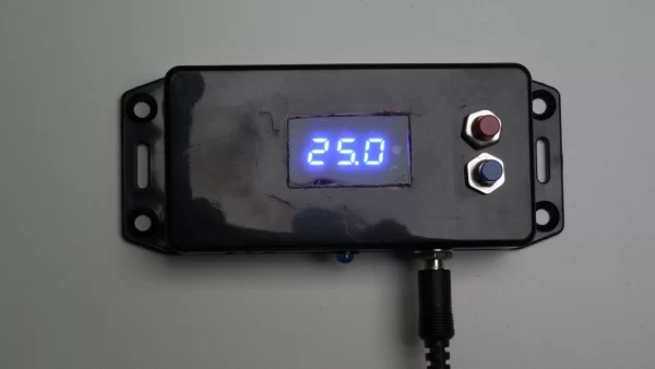
- Show the measured and desired temperature on a 7-segment LED display
- Switch the RF Panel Relay on and off based on the room temperature and the desired temperature
As always I used a PIC microcontroller and created all software without using any specific libraries. Arduino fans can use of course do the same or use the libraries that are available for e.g. the DS18B20 temperature sensor.
Step 1: Transmitting Messages Via RF
As said his system uses a simple 433 MHz RF transmitter and 433 MHz RF receiver to send messages from the RF Thermostat to the RF Panel Relays. I could have used a system based on the nRF24L01 but I found that too complex and I did not really need a two-way link. So after having searched on the Internet which kind of systems and protocols are normally used on a 433 MHz link, I designed my homebrew protocol that matched my needs. This is a one way system but seemed to be reliable enough for this application.
The protocol I designed is given in the picture.
The protocol uses Manchester encoding. After two preamble bytes and a synchronization byte a few bytes are transmitted. The ‘Key’ is used as a kind of scrambling so that the message changes every time it is transmitted. One byte is reserved for address and command and a checksum byte is used to validate the correctness of the message. Since I have only one RF receiver, one address is used. Two commands are used in the transmission, one command for ‘on’ and one command for ‘off’.
Since this is a one-way system, the Thermostat will re-transmit a message every 2 minutes, using a different key for each transmission. This ‘alive’ signal is needed to keep the Infra Red panel switched on if needed. More on this in the Instructable of the RF Panel Relay.
Step 2: Required Components
You need to have the following components for this project:
- A piece of breadboard
- PIC microcontroller 16F1823
- 74HC595 Shift Register
- DS18B20 temperature sensor
- 433 MHz RF transmitter, like the STX882 ASK Wireless Transmitter Module
- 78L05 voltage regulator
- 3 * 7-segment Display
- 3 * 100nF ceramic capacitors
- 1uF electrolytic capacitor
- 2 * 33k, 8 * 220 Ohm, 1 * 4k7, 3 * 1k and 1 * 330 Ohm resistors
- 3 * BC557 transistor
- Blue LED
- 2 * push-button switches
- DC Jack
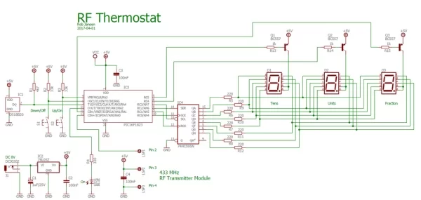
See the schematic diagram on how to connect the components.
Step 3: Building the Electronics
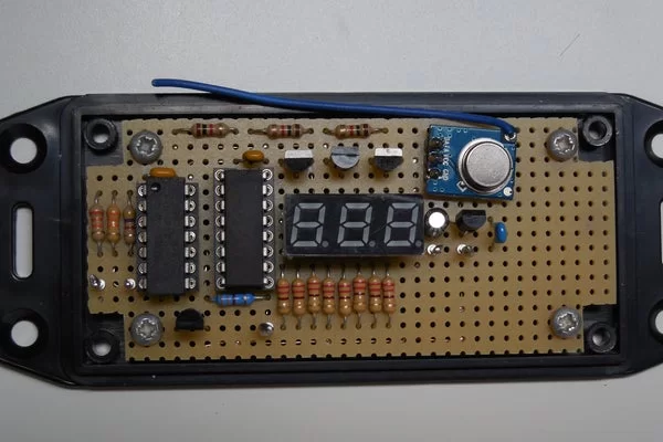
You can build the circuit on a breadboard. In the pictures you can see the circuit as I build it on the breadboard. The whole circuit was built in a plastic housing. You must make sufficient holes in the housing for the air flow and for the temperature sensor to be able to measure the correct room temperature.
When the 7-segment and Blue LED are on the circuit draws about 55 mA. For the power supply I used an external DC adapter. It is best to use an input voltage of about 8 Volt and not higher as for the 78L05 not to become too hot. Note that the software switches the display off after 30 seconds which lowers the power consumption when the device is on.
Step 4: The Software
As already mentioned, the software is written for a PIC16F1823. It was written in JAL. Since I did not use any specific libraries the total code size is 1500 bytes which fits nicely in the 2k program flash memory this specific controller has.
The software performs the following main tasks:
- Measuring the room temperature using the DS18B20. For this I implemented the one-wire protocol in JAL.
- Show the temperature on the 7-segment LED displays. These displays are multiplexed in software and are controlled via the 74HC595 shift register since there were insufficient pins available on the controller to control the 7-segments directly. After 30 seconds the software switches the display off.
- Store a preset temperature. For this an up switch and a down switch are used. During this so-called program mode the 7-segment LED display will blink. The program mode is started by pressing the up switch when the device is on and is stopped when no button is pressed for 10 seconds. The preset temperature is stored as long as the Thermostat is powered on.
- Sending the RF message to control the RF Panel Relay if the Thermostat is switched on. This message is repeated every two minutes as to keep the link with the RF Panel Relay alive. The transmission of the RF message is completely interrupt based
- The Thermostat can be switched on and off using the up switch and down switch. The blue LED will be on when the Thermostat is switched on. When switched on, the preset temperature will be compared with the room temperature and based on the values it will switch the RF Panel Relay on or off. Switching the Thermostat off will only switch off the 7-Segment Display and the blue LED and no RF messages will be sent anymore. The device will, however, keep the preset temperature that is used when switching the device on again.
The PIC controller runs on an internal clock with a frequency of 32 MHz. The Intel Hex is attached.
The following video shows the first set-up with the RF Thermostat on a prototype board and the RF Panel Relay on a breadboard. It demonstrates switching the RF Thermostat on and switching the RF Panel Relay on by increasing the desired temperature on the RF Thermostat. On the RF Panel Relay the green LED indicates that a valid message was received where the red LED indicates that the relay – and so the Infra Red panel – is switched on.
Attachments
Step 5: The Tests
Several tests were performed to test the reliability of the system:
- Distance test. The RF signal only needs to bridge a few meters since both the Thermostat and the Panel Relays are in the same room. With only a short wire as antenna the system could even bridge a distance from my addict to the living room which is way more than needed
- Reliability test. This test was to see if messages were missed because of disturbances on the 433 MHz channel. Although other signals were present I could not detect that messages were lost because of this
- False detection test. As said, there are signals present on the 433 MHz channel. In this test I did not send any messages but checked if the RF Panel Relay was activated by any other signal on the 433 MHz channel. This did not happen after a measurement of a whole day
So this system does what it needs to do and it works well. Don’t forget to look at the Instructable of the RF Panel Relay for the receiving part of this project.
Have fun building your own project and looking forward to your reactions.
Source: RF Thermostat
- Why was this RF Thermostat project built?
The author needed a simple system because commercial thermostats suffered from reset problems that caused loss of connection with the relay. - How does the system transmit messages?
It uses a custom homebrew protocol over a 433 MHz link with Manchester encoding, including preamble bytes, a synchronization byte, a scrambling key, address, command, and checksum. - What microcontroller is used in the design?
The project utilizes a PIC16F1823 microcontroller running at an internal clock frequency of 32 MHz. - Can I use Arduino instead of the PIC microcontroller?
Yes, the article states that Arduino fans can replicate the project using available libraries for components like the DS18B20 sensor. - How often does the thermostat re-transmit the signal?
The thermostat sends an alive signal every 2 minutes to keep the infrared panel switched on if necessary. - What happens to the display after 30 seconds?
The software automatically switches off the 7-segment display and blue LED after 30 seconds to lower power consumption. - How do you enter the program mode to set the desired temperature?
You start program mode by pressing the up switch while the device is on, and it ends automatically if no button is pressed for 10 seconds. - Does the device store the preset temperature when powered off?
No, the preset temperature is stored only as long as the thermostat remains powered on. - What voltage should be used for the power supply?
An input voltage of about 8 Volt is recommended for the DC adapter to prevent the 78L05 voltage regulator from overheating.