Summary of RF Panel Relay
This article details the construction of an RF Panel Relay, a companion device to an RF Thermostat. It uses a PIC12F615 microcontroller to decode 433 MHz RF signals and control a mains-powered relay. The system automatically switches off the relay if no signal is received for 10 minutes or if a software hang-up occurs, ensuring safety and reliability without using external libraries.
Parts used in the RF Panel Relay:
- Breadboard
- PIC microcontroller 12F615
- 433 MHz RF receiver (SRX882)
- Fuse holder + fuse 6.3A/250V
- 2 x 100nF ceramic capacitors
- Resistors (33k, 220 Ohm, 180 Ohm, 1k)
- Red LED and Green LED
- Diode 1N4148
- BC640 transistor
- 5 Volt relays
- 5 Volt power supply
This project described the second part of the following project:
- An RF Thermostat as described in the following Instructurable: https://www.instructables.com/id/RF-Thermostat/
- An RF Panel Relay, described in this Instructable
For an introduction on this project first read the description of the RF Thermostat.
In short the RF Panel Relay has the following functions:
- Decode an RF message received via an 433 MHz RF link according to the protocol described in the RF Thermostat Instructable
- Control a relay based on the contents of the received RF message
- Switch off the relay if no RF message is received after a certain time frame
As always I used a PIC microcontroller and created all software without using any specific libraries. Arduino fans can use of course do the same.
Step 1: Required Components
You need to have the following components for this project:
- A piece of breadboard
- PIC microcontroller 12F615
- 433 MHz RF receiver, like the SRX882 433MHz ASK Superhetrodyne receiver
- Fuse holder + fuse 6,3A/250V
- 2 * 100nF ceramic capacitor
- 1 * 33k, 1 * 220 Ohm, 1 * 180 Ohm, 1 * 1k resistors
- 1 * red LED, 1 * green LED
- Diode 1N4148
- BC640 transistor
- Relays operating on +5 Volt and capable of switch sufficient mains power. I used: https://www.aliexpress.com/item/5pcs-SRD-05VDC-SL-C-5VDC-10A-Power-relay-PCB-Type-T73-5V-5-feet-SRD/32653259475.html?spm=2114.13010608.0.0.l3L3LV
- 5 Volt Power supply sufficient to power the circuit. I used: https://www.aliexpress.com/item/5V-700mA-3-5W-AC-DC-Precision-Buck-Converter-AC-220v-to-5v-DC-step-down/32649591757.html?spm=2114.13010608.0.0.wsZU1q
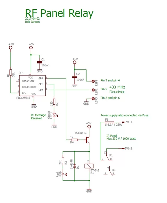
See the schematic diagram on how to connect the components.
Step 2: Building the Electronics
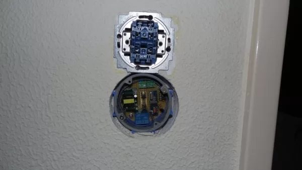
You can build the circuit on a breadboard but be very careful with the Fuse and the Relays that switch the mains power for the Infra-Red Panel. Do not touch the mains power in any way!
In the picture you can see the circuit as I build it on the breadboard. The whole circuit was built as to fit in a welding box.
Step 3: The Software
As already mentioned, the software is written for a PIC12F615. It was written in JAL. Since I did not use any specific libraries the total code size is 445 bytes which fits nicely in the 1k program flash memory this specific controller has.
The software performs the following main tasks:
- Decoding the RF messages. For this it uses a capture timer that captures the duration of the bits. The decoding routine works completely interrupt based and uses each bit level change of the Manchester encoded RF message by constantly changing the interrupt edge level. This increases the reliability of the decoding routine
- Switch on the relay when the ‘on’ command is received or switch the relay off when the ‘off’ command is received
- Switch off the relay when no more messages are received for a period of 10 minutes. As mentioned in the Instructable of the RF Thermostat, the RF message is repeated every 2 minutes to keep the connection ‘alive’. If for some reason the relay is switched on but the RF Thermostat is switched off without having sent an ‘off’ command, the software will always switch off the relay after 10 minutes
- Kicking the watch dog on a frequent basis. The watchdog will not reset the controller if it is triggered each 18 ms. The main program uses a loop time of 1 ms in which it kicks the watchdog and so prevents the dog from barking. The watchdog is used to prevent any hang-ups in the software and in case a hang-up should happen, the program is reset and the relay is switched off
The PIC controller runs on an internal clock with a frequency of 8 MHz. The Intel Hex file is attached.
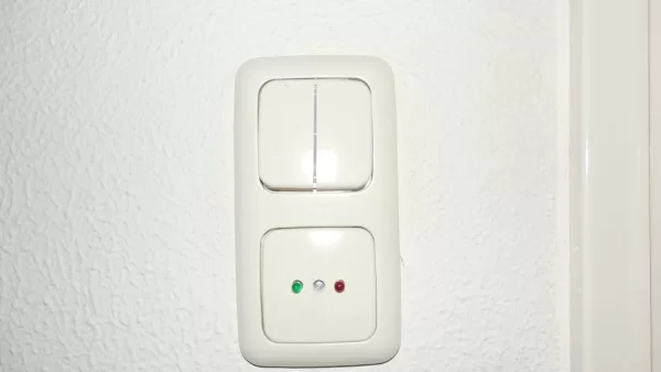
The video shows the final set-up with the RF Thermostat in a housing and the RF Panel Relay in the welding box with cover. It demonstrates switching the RF Thermostat on and switching the RF Panel Relay on by increasing the desired temperature on the RF Thermostat. On the RF Panel Relay the green LED indicates that a valid message was received where the red LED indicates that the relay – and so the Infra Red panel – is switched on.
Have fun building your own project and looking forward to your reactions.
Attachments
Source: RF Panel Relay
- What functions does the RF Panel Relay perform?
It decodes RF messages via a 433 MHz link, controls a relay based on message content, and switches off the relay if no message is received after a set time. - Can I use an Arduino instead of the PIC microcontroller?
Yes, the author states that Arduino fans can use their own method, though this project specifically uses a PIC microcontroller written in JAL. - How long must pass without an RF message before the relay switches off?
The relay switches off if no RF messages are received for a period of 10 minutes. - What frequency does the RF receiver operate on?
The project uses a 433 MHz RF receiver, such as the SRX882 model. - How does the software ensure reliability during decoding?
The decoding routine is interrupt-based and changes the interrupt edge level with every bit level change of the Manchester encoded RF message. - What happens if the software hangs up?
The watchdog timer will reset the controller, causing the program to restart and the relay to switch off. - What clock frequency does the PIC controller run at?
The PIC controller runs on an internal clock with a frequency of 8 MHz. - Which programming language was used for the software?
The software was written in JAL without using any specific libraries.