Summary of Real Time Clock Circuit using Mircocontroller
This article details a low-power 24-hour (or 12-hour) digital clock circuit built around a PIC16F84A microcontroller. The device features a seven-segment display, three push buttons for time setting and resetting, and runs on rechargeable batteries with current draw under 100mA. Users can switch between time formats by flashing different hex files onto the chip.
Parts used in the Digital Clock Circuit:
- PIC 16F84A Microchip
- Transistor BC548 (4 units)
- Resistors (180R-9 units, 10K, 1K-4 units)
- LED
- Capacitor (22pF, 2 units)
- Push button (3 units)
- Crystal 4MHz
- Common cathode seven segment display (4 units)
Here I am going to teach you a simple circuit of 24 hour digital clock display that can also be used in 12 hour format by simply loading the corresponding clock program. You can download the hex files for both 12 hour format and 24 hour time system from the link given in this article. Coming to the technical part, main component of the circuit is a PIC16f84A microchip; it generates the one second clock to run the device and also controls the seven segment display. Three push buttons are also provided to set the time; one for reset by which you can reset the complete circuit as it is connected to the reset pin of PIC microcontroller. Other two push buttons are for setting hour and minute. By Pressing these button continuously you can increment hour and minutes.
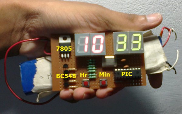
The main feature of this real time clock circuit is that it only draws less than 100mA, so it can be run with rechargeable batteries. By increasing the value of resistors connected to the seven segment display you can decrease the current gain. 24(international time clock) to 12 hour time clock conversion can be done simply by burning the PIC microchip with the corresponding hex file.
Download Hex file of real time embedded C
The hex file for both 12 hour and 24 hour time clock are available at our Download Center.
(In case you are facing any problem in downloading the files, use the comment box at the bottom
Download link Updated: 14/June/2013)
Circuit diagram of Pacific Time clock
Click on the circuit for enlarged view
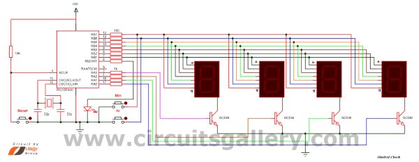
Components Required
- PIC 16F84A
- Transistor BC548 (4-Nos)
- Resistor (180R-9Nos,10K,1K-4Nos)
- LED
- Capacitor(22pf2Nos)
- Push button (3-Nos)
- Crystal 4MHz
- Common cathode seven segment display (4-Nos)
For more deteail: Real Time Clock Circuit using Mircocontroller
- What is the main component of this clock circuit?
The main component is a PIC16f84A microchip. - Can this clock operate in 12-hour format?
Yes, it can be used in 12-hour format by loading the corresponding clock program. - How many push buttons are provided for setting the time?
Three push buttons are provided for resetting, setting hours, and setting minutes. - Does this circuit consume less power than 100mA?
Yes, the circuit draws less than 100mA, allowing it to run with rechargeable batteries. - How can I convert the clock from 24-hour to 12-hour format?
You can do this simply by burning the PIC microchip with the corresponding 12-hour hex file. - What crystal frequency is required for this project?
A 4MHz crystal is required for the circuit. - How do you increment the hour and minute values?
You press the respective buttons continuously to increment the hour and minutes. - Where can I download the hex files for this project?
The hex files are available at the Download Center mentioned in the article.