Summary of Connect CAN-SPI with PIC Controller
Summary: The article documents mikroC PRO for PIC's CANSPI library for interfacing PIC microcontrollers with mikroElektronika's CANSPI Add-on boards (MCP2515/MCP2510) over SPI. It describes CAN features, message formats, required global pins, library routines (initialize, mode, baudrate, masks/filters, read/write), usage requirements, examples, and notes that SPI-based CANSPI is slower than native CAN and requires proper termination and cabling.
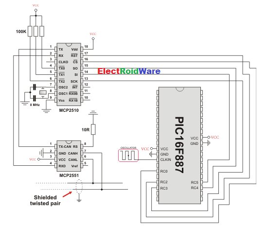
Parts used in the CANSPI Project:
- PIC microcontroller with SPI module
- mikroElektronika CANSPI Add-on board (MCP2515 or MCP2510)
- SPI interface (hardware SPI module on MCU)
- Chip Select connection (CanSpi_CS pin)
- Reset connection (CanSpi_Rst pin)
- Chip Select direction pin (CanSpi_CS_Direction)
- Reset direction pin (CanSpi_Rst_Direction)
- Shielded twisted pair CAN cable with proper termination
- Power supply for MCU and CANSPI board
The SPI module is available with a number of the PIC compliant MCUs. The mikroC PRO for PIC provides a library (driver) for working with mikroElektronika’s CANSPI Add-on boards (with MCP2515 or MCP2510) via SPI interface.
The CAN is a very robust protocol that has error detection and signalization, self–checking and fault confinement. Faulty CAN data and remote frames are re-transmitted automatically, similar to the Ethernet.
In the mikroC PRO for PIC, each routine of the CAN library has its own CANSPI counterpart with identical syntax. For more information on Controller Area Network, consult the CAN Library. Note that an effective communication speed depends on SPI and certainly is slower than “real” CAN.
Data transfer rates depend on distance. For example, 1 Mbit/s can be achieved at network lengths below 40m while 250 Kbit/s can be achieved at network lengths below 250m. The greater distance the lower maximum bitrate that can be achieved. The lowest bitrate defined by the standard is 200Kbit/s. Cables used are shielded twisted pairs.
CAN supports two message formats:

 Important :
- Consult the CAN standard about CAN bus termination resistance.
- An effective CANSPI communication speed depends on SPI and certainly is slower than “real” CAN.
- The library uses the SPI module for communication. User must initialize appropriate SPI module before using the CANSPI Library.
- For MCUs with two SPI modules it is possible to initialize both of them and then switch by using the SPI_Set_Active routine.
- CANSPI module refers to mikroElektronika’s CANSPI Add-on board connected to SPI module of MCU.
Library Dependency Tree

External dependencies of CANSPI Library
| The following variables must be defined in all projects using CANSPI Library: | Description : | Example : |
|---|---|---|
extern sfr sbit CanSpi_CS; |
Chip Select line. | sbit CanSpi_CS at RC0_bit; |
extern sfr sbit CanSpi_Rst; |
Reset line. | sbit CanSpi_Rst at RC2_bit; |
extern sfr sbit CanSpi_CS_Direction; |
Direction of the Chip Select pin. | sbit CanSpi_CS_Direction at TRISC0_bit; |
extern sfr sbit CanSpi_Rst_Direction; |
Direction of the Reset pin. | sbit CanSpi_Rst_Direction at TRISC2_bit; |
Library Routines
- CANSPISetOperationMode
- CANSPIGetOperationMode
- CANSPIInitialize
- CANSPISetBaudRate
- CANSPISetMask
- CANSPISetFilter
- CANSPIRead
- CANSPIWrite
CANSPISetOperationMode
| Prototype | void CANSPISetOperationMode(char mode, char WAIT); |
|---|---|
| Returns | Nothing. |
| Description | Sets the CANSPI module to requested mode. Parameters :
|
| Requires | The CANSPI routines are supported only by MCUs with the SPI module. MCU has to be properly connected to mikroElektronika’s CANSPI Extra Board or similar hardware. See connection example at the bottom of this page. |
| Example |
// set the CANSPI module into configuration mode (wait inside CANSPISetOperationMode until this mode is set) CANSPISetOperationMode(_CANSPI_MODE_CONFIG, 0xFF); |
CANSPIGetOperationMode
| Prototype | char CANSPIGetOperationMode(); |
|---|---|
| Returns | Current operation mode. |
| Description | The function returns current operation mode of the CANSPI module. Check CANSPI_OP_MODE constants or device datasheet for operation mode codes. |
| Requires | The CANSPI routines are supported only by MCUs with the SPI module. MCU has to be properly connected to mikroElektronika’s CANSPI Extra Board or similar hardware. See connection example at the bottom of this page. |
| Example |
// check whether the CANSPI module is in Normal mode and if it is do something.
if (CANSPIGetOperationMode() == _CANSPI_MODE_NORMAL) {
  ...
}
|
CANSPIInitialize
| Prototype | void CANSPIInitialize( char SJW, char BRP, char PHSEG1, char PHSEG2, char PROPSEG, char CANSPI_CONFIG_FLAGS); |
|---|---|
| Returns | Nothing. |
| Description | Initializes the CANSPI module. Stand-Alone CAN controller in the CANSPI module is set to:
|
| Requires | Global variables :
must be defined before using this function. |
| Example |
// CANSPI module connections
sbit CanSpi_CS  at  RC0_bit;
sbit CanSpi_CS_Direction  at  TRISC0_bit;
sbit CanSpi_Rst at  RC2_bit;
sbit CanSpi_Rst_Direction at  TRISC2_bit;
// End CANSPI module connections

// initialize the CANSPI module with the appropriate baud rate and message acceptance flags along with the sampling rules
char CanSPi_Init_Flags;
  ...
  CanSPi_Init_Flags = _CANSPI_CONFIG_SAMPLE_THRICE &  // form value to be used
                   _CANSPI_CONFIG_PHSEG2_PRG_ON &  // with CANSPIInitialize
                   _CANSPI_CONFIG_XTD_MSG &
                   _CANSPI_CONFIG_DBL_BUFFER_ON &
                   _CANSPI_CONFIG_VALID_XTD_MSG;
  ...
  SPI1_Init();                                // initialize SPI module
  CANSPIInitialize(1,3,3,3,1,CanSpi_Init_Flags);  // initialize external CANSPI module
|
CANSPISetBaudRate
| Prototype | void CANSPISetBaudRate( char SJW, char BRP, char PHSEG1, char PHSEG2, char PROPSEG, char CANSPI_CONFIG_FLAGS); |
|---|---|
| Returns | Nothing. |
| Description | Sets the CANSPI module baud rate. Due to complexity of the CAN protocol, you can not simply force a bps value. Instead, use this function when the CANSPI module is in Config mode.SAM, SEG2PHTS and WAKFIL bits are set according to CANSPI_CONFIG_FLAGS value. Refer to datasheet for details.Parameters:
|
| Requires | The CANSPI module must be in Config mode, otherwise the function will be ignored. The CANSPI routines are supported only by MCUs with the SPI module. MCU has to be properly connected to mikroElektronika’s CANSPI Extra Board or similar hardware. See connection example at the bottom of this page. |
| Example |
// set required baud rate and sampling rules
char canspi_config_flags;
...
CANSPISetOperationMode(CANSPI_MODE_CONFIG,0xFF);              // set CONFIGURATION mode (CANSPI module mast be in config mode for baud rate settings)
canspi_config_flags = _CANSPI_CONFIG_SAMPLE_THRICE &
                   _CANSPI_CONFIG_PHSEG2_PRG_ON &
                   _CANSPI_CONFIG_STD_MSG       &
                   _CANSPI_CONFIG_DBL_BUFFER_ON &
                   _CANSPI_CONFIG_VALID_XTD_MSG &
                   _CANSPI_CONFIG_LINE_FILTER_OFF;
CANSPISetBaudRate(1, 1, 3, 3, 1, canspi_config_flags);
|
CANSPISetMask
| Prototype | void CANSPISetMask(char CANSPI_MASK, long val, char CANSPI_CONFIG_FLAGS); |
|---|---|
| Returns | Nothing. |
| Description | Configures mask for advanced filtering of messages. The parameter value is bit-adjusted to the appropriate mask registers.Parameters:
|
| Requires | The CANSPI module must be in Config mode, otherwise the function will be ignored. See CANSPISetOperationMode. The CANSPI routines are supported only by MCUs with the SPI module. MCU has to be properly connected to mikroElektronika’s CANSPI Extra Board or similar hardware. See connection example at the bottom of this page. |
| Example |
// set the appropriate filter mask and message type value CANSPISetOperationMode(_CANSPI_MODE_CONFIG,0xFF); // set CONFIGURATION mode (CANSPI module must be in config mode for mask settings) // Set all B1 mask bits to 1 (all filtered bits are relevant): // Note that -1 is just a cheaper way to write 0xFFFFFFFF. // Complement will do the trick and fill it up with ones. CANSPISetMask(_CANSPI_MASK_B1, -1, _CANSPI_CONFIG_MATCH_MSG_TYPE & _CANSPI_CONFIG_XTD_MSG); |
CANSPISetFilter
| Prototype | void CANSPISetFilter(char CANSPI_FILTER, long val, char CANSPI_CONFIG_FLAGS); |
|---|---|
| Returns | Nothing. |
| Description | Configures message filter. The parameter value is bit-adjusted to the appropriate filter registers.Parameters:
|
| Requires | The CANSPI module must be in Config mode, otherwise the function will be ignored. The CANSPI routines are supported only by MCUs with the SPI module. MCU has to be properly connected to mikroElektronika’s CANSPI Extra Board or similar hardware. See connection example at the bottom of this page. |
| Example |
// set the appropriate filter value and message type CANSPISetOperationMode(_CANSPI_MODE_CONFIG,0xFF); // set CONFIGURATION mode (CANSPI module must be in config mode for filter settings) /* Set id of filter B1_F1 to 3: */ CANSPISetFilter(_CANSPI_FILTER_B1_F1, 3, _CANSPI_CONFIG_XTD_MSG); |
CANSPIRead
| Prototype | char CANSPIRead(long *id, char *rd_data, char *data_len, char *CANSPI_RX_MSG_FLAGS); |
|---|---|
| Returns |
|
| Description | If at least one full Receive Buffer is found, it will be processed in the following way:
Parameters:
|
| Requires | The CANSPI module must be in a mode in which receiving is possible. The CANSPI routines are supported only by MCUs with the SPI module. MCU has to be properly connected to mikroElektronika’s CANSPI Extra Board or similar hardware. See connection example at the bottom of this page. |
| Example |
// check the CANSPI module for received messages. If any was received do something.
char msg_rcvd, rx_flags, data_len;
char data[8];
long msg_id;
...
CANSPISetOperationMode(_CANSPI_MODE_NORMAL,0xFF);                  // set NORMAL mode (CANSPI module must be in mode in which receive is possible)
...
rx_flags = 0;                                                // clear message flags
if (msg_rcvd = CANSPIRead(msg_id, data, data_len, rx_flags)) {
  ...
}
|
 CANSPIWrite
| Prototype | char CANSPIWrite(long id, char *wr_data, char data_len, char CANSPI_TX_MSG_FLAGS); |
|---|---|
| Returns |
|
| Description | If at least one empty Transmit Buffer is found, the function sends message in the queue for transmission. Parameters:
|
| Requires | The CANSPI module must be in mode in which transmission is possible. The CANSPI routines are supported only by MCUs with the SPI module. MCU has to be properly connected to mikroElektronika’s CANSPI Extra Board or similar hardware. See connection example at the bottom of this page. |
| Example |
// send message extended CAN message with the appropriate ID and data char tx_flags; char data[8]; long msg_id; ... CANSPISetOperationMode(_CANSPI_MODE_NORMAL,0xFF); // set NORMAL mode (CANSPI must be in mode in which transmission is possible) tx_flags = _CANSPI_TX_PRIORITY_0 & _CANSPI_TX_XTD_FRAME; // set message flags CANSPIWrite(msg_id, data, 2, tx_flags); |
For more detail: Connect CAN-SPI with PIC Controller
- What library provides CAN-over-SPI support for PIC in mikroC PRO?
The CANSPI library in mikroC PRO for PIC provides drivers for mikroElektronika's CANSPI Add-on boards (MCP2515 or MCP2510) via SPI. - Which MCU feature is required to use the CANSPI library?
An MCU with the SPI module is required. - What global variables must be defined to use the CANSPI library?
CanSpi_CS, CanSpi_Rst, CanSpi_CS_Direction, and CanSpi_Rst_Direction must be defined. - How do you set the CANSPI module operation mode?
Use CANSPISetOperationMode(mode, WAIT) where mode is a CANSPI_OP_MODE constant and WAIT controls blocking verification. - Can you set the baud rate while the CANSPI module is running normally?
No. CANSPISetBaudRate must be called while the module is in Config mode; otherwise it is ignored. - How do you configure message filtering and masking?
Use CANSPISetFilter and CANSPISetMask functions while the module is in Config mode to set filter and mask registers with CANSPI_CONFIG_FLAGS. - What does CANSPIRead return when a message is received?
It returns 0xFF if a Receive Buffer is full (message received) and 0 if nothing is received. - What does CANSPIWrite return if a transmit buffer is available?
It returns 0xFF if at least one Transmit Buffer is available and 0 if all are busy. - Are CAN data rates affected by cable length?
Yes. Higher bitrates like 1 Mbit/s are for short lengths (below ~40m); lower bitrates for longer distances; the standard lowest bitrate is 20 Kbit/s. - Is CANSPI communication as fast as native CAN?
No. Effective CANSPI communication speed depends on SPI and is slower than real CAN.