Summary of Reading Nintendo 64 controller with PIC microcontroller
This article details a project to interface old Nintendo 64 controllers with a PIC microcontroller for controlling other devices. The author explains the hardware setup using a PIC18F2550, including connections for power, data, and LEDs, along with the specific signal timing required for communication. The guide covers the serial protocol, bit-level assembly programming for generating polling signals, and the structure of the 32-bit data array returned by the controller.
Parts used in the N64 Controller Interface Project:
- N64 Controllers
- PIC18F2550 Microcontroller
- LEDs (three units)
- 3.3V Voltage Regulator
- Screw Connector
- Header (JP1) for PICKit2
- PICKit2 Programmer
- Wireless RF Transmitter
- Perfboard
I have a few old N64 controllers lying around and figured that it would be pretty cool to use them to control other things. In this article I will describe in detail every step I took to achieve this. I’ve used a PIC microcontroller, but it should not be too hard to port the code to any other architecture.
Connector
The N64 controller has three connections. From right to left with the round side up: Ground, Data and VCC (3.3V). Just plug some cables in the holes and you’re ready to go.
Hardware
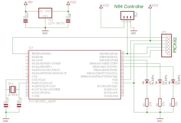
The circuit I created for reading out the controller is shown in the schematic below. It is based around a PIC18F2550. I chose a pic from the 18F range, because I am interested in the USB capabilities, as I might try to use the N64 controller with a computer some day (future article maybe?). I did however limit my oscillator frequency to 20 MHz, so that everything should work on a 16F pic as well if you don’t need USB.
I’ve connected three LED’s to RB5, RB4 and RB3. They will provide some visual feedback so we can see if everything works properly. A 3.3V voltage regulator provides the voltage for the board. The maximum voltage the N64 controller can handle is 3.6V, so don’t exceed that. If you use 5V you will risk frying your controller. The N64 controller is connected to the board with a simple screw connector. Here the supply voltage is given, and the data pin is connected to the RB7 pin of the PIC18F2550.
 I’ve also connected a header (JP1) for the PICKit2. This allows me to program the PIC without having to take it out of the circuit (ICSP). At the moment it also provides the supply voltage to the board because I am to lazy to find a good power supply. Make sure you set the PICKit to 3.3V instead of the default 5V for the reason I mentioned earlier.
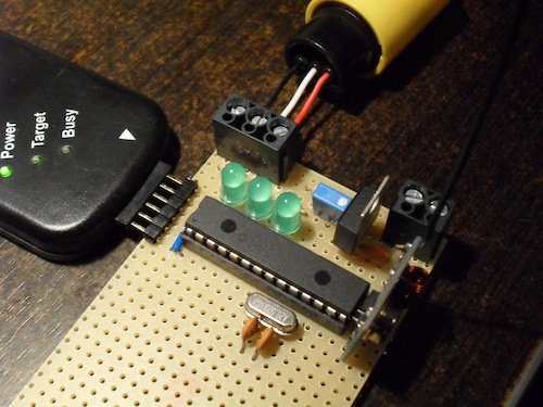
The image below shows the fully built circuit built on perfboard. The rectangular thing to the right of the microcontroller is a wireless RF transmitter. I will talk about this in a next article, but it is of no importance to us now.
Interface
Now we’re going to take a quick look at the communication with the Nintendo 64 controller. The interface looks a little bit like one wire, but is still different. It’s a serial interface, which means that all the signals discussed here, will take place on one pin: the DATA (middle) pin of the connector (white wire in the pictures above).
Signal Shapes
The signal shapes used by the N64 controller for one and zero are shown below. As you can see these signals are very fast with a period of 4 uS and a resolution of 1 us! On a PIC microcontroller, one instruction cycle equals 4 oscillator cycles, which means that with a 20 MHz oscillator, 1 uS takes only 5 instruction cycles! To generate these signals, we will need a low-level programming language like assembly, as C just won’t cut it. I will give as much information as needed, so if this is your first experience with assembly, you will be able to follow easily. A good reference for the PIC instruction set can be found here: PIC Instructions.
|
|
Below both signal shapes I have included a very simple program to generate the signal in asm (of course there are other possibilities e.g. with bsf and bcf). There are only three different instructions used:
- movlw: place the value that you indicate in the W register.
- movwf: place the value that is currently in the W register, in the register that you indicate.
- nop: do nothing.
It’s easy to see that a combo of movlw with movwf can set a pin by modifying the PORTB register. As our N64 controller is connected to pin RB7, we set this pin high by sending the binary signal 0b10000000 to PORTB, which is 0x80 in hexadecimals. Ofcouse sending 0x00 makes the pin 0.
All three instructions we used take 1 instruction cycle (check the PIC 18F instruction set here). This means that it is very easy to count every step. As I said previously: 1 uS takes 5 instruction cycles. That means that, to generate a zero, we have to set pin RB7 low, wait for 15 instructions, and then set it high for 5 instructions. I have counted and indicated the instructions that the pin is high with a bold font, and the instructions that it is low with a gray font. You have to think about these code blocks as if a lot of them are cascaded after each other, so that the first instruction of every code block, is actually the last instruction of the previous block. This will make the timing exact.
Of course this code will only work with an oscillator frequency of 20 MHz on a PIC microcontroller. If you have another oscillator you can easily calculate how many instruction cycles you need for 1 uS though. If you are using another architecture (AVR, ARM, …) you have to figure out how many oscillator cycles one instruction takes first (it is usually less than 4, which makes it easier to use C on those architectures).
Controller Data
The N64 controller data consists of a 32 bit (4 bytes), which gives you the status (on/off) of all buttons and the joystick position (2 bytes) and one stop bit. The array is built up like this:
0 1 2 3 4 5 6 7 8 9 10 11 12 13 14 15 16-23 24-31 32 |
A B Z Start Up Down Left Right / / L R C-Up C-Down C-Left C-Right X-Axis Y-Axis Stop bit (1) |
e.g. if the Z button is pressed, the 3th element of this array will read one etc.
The position of the joystick can be determined from the two bytes given by “X-Axis” and “Y-Axis”.
Polling Signal
To receive the data array from the controller, a polling signal has to be sent first. This signal is: 0b000000011 (9 bits). After this signal is sent, the controller will respond with the 33 bit array (4 bytes + stop bit). This is shown in the picture below. The B-button is pushed so the second bit of the response is 1.
The assembly code used to generate the polling signal is shown below. Instead of copy pasting 7 zero blocks and 2 one blocks from above (which would work perfectly). I used the decfsz (decrement file, skip if zero) instruction to create loops. This instruction will decrement the register you indicate, and skip the next instruction if this register becomes zero. It takes two instruction cycles if it skips, else one! The registers d1, d2 and d3 can be defined in the beginning of the program using a cblock. After the decfsz instruction there is a goto instruction, which will move the program counter to the instruction after the word that you have indicated. It should be clear to see how a combo of these two instructions create a loop.
All instructions use one instruction cycle (4 oscillator cycles), except for: goto, which uses 2 instruction cycles. Of course decfsz also takes two instruction cycles when it skips, as mentioned earlier. Its not so hard to distinguish the two code blocks we saw earlier, only this time I tried to make them a little shorter by replacing some of the nop’s with loops (zeroloop, oneloop). If you take the time to count the instruction cycles carefully for each loop (which I strongly recommend), you will see that there would be no difference if we would copy paste 7 zero’s and 2 one’s from the previous code.
 bcf TRISB, 7 ; make RB7 output ; 0b000000011 movlw 0x07 ; number of zeros that need to be sent movwf d2 movlw 0x02 ; number of ones that need to be sent movwf d3 zero movlw 0x00 movwf PORTB movlw 0x03 movwf d1 zeroloop ; 3 instruction cycles * 3 = 9 decfsz d1, f goto zeroloop nop nop movlw 0x80 movwf PORTB decfsz d2 goto zero one movlw 0x00 movwf PORTB nop nop nop movlw 0x80 movwf PORTB movlw 0x02 movwf d1 oneloop ; 4 instruction cycles * 2 = 8 nop decfsz d1, f goto oneloop decfsz d3 goto one
note: the pin RB7 is set to function as an output pin by setting the TRISB register (duh!).
In the image below you can see a picture of an oscilloscope measuring the polling signal generated with the code above. You can clearly see the signal 0b00000011.
This is a close up of the 7th (0) and 8th (1) bit of the polling signal. The timebase is set to 1 uS. As you can see, the signal is extremely correct.
If you now connect the N64 controller, you should see that it responds immediately after the polling signal was sent. I have shown this in the pictures below. In the second picture the B button is pressed, so you can see that the second bit of the response is a 1. Once you attach the controller, the signal wil deform because of its impedance. This is normal and not really a problem for us.
For more detail: Reading Nintendo 64 controller with PIC microcontroller
- What are the three connections on an N64 controller?
The connections from right to left with the round side up are Ground, Data, and VCC (3.3V). - Can I use a 5V supply for the N64 controller?
No, you must not exceed 3.6V as using 5V risks frying your controller. - Which pin on the PIC18F2550 is connected to the N64 controller data pin?
The data pin is connected to the RB7 pin of the PIC18F2550. - Why is assembly language recommended over C for this project?
Assembly is needed because the signal periods are very fast (4 uS), and C cannot easily handle the precise instruction cycles required. - How many bits make up the data array sent by the N64 controller?
The data consists of a 32-bit array which includes button status, joystick position, and one stop bit. - What is the polling signal required to receive data from the controller?
The polling signal is 0b000000011, which consists of 9 bits. - What oscillator frequency was used in the example code?
The example uses a 20 MHz oscillator frequency. - What voltage should be set on the PICKit2 programmer?
You must set the PICKit2 to 3.3V instead of the default 5V.