Summary of PSU Burner – a power supply tester
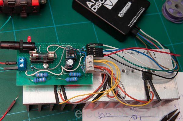
This article describes a DIY constant current load for testing power supply endurance. The author details two design iterations, starting with a simple OP-AMP and MOSFET setup that failed due to an avalanche event. The improved "Take 2" version uses an operational amplifier (U1A) to drive a MOSFET (Q1), maintaining constant current via feedback across a sense resistor (R6). It features both external control via an Analog Discovery waveform generator and an internal adjustable mode using a voltage regulator and potentiometer.
Parts used in the Constant Current Load Project:
- OP-AMP (U1A)
- MOSFETs (Q1 and others)
- Resistors (R2, R3, R5, R6)
- Potentiometer (RV1)
- 5V Regulator
- Analog Discovery
- Signal Generator
- Fuse
Intro
However, I wanted to make a better one: one that I could hook up to my Analog Discovery and generate a test waveform to be able to connect and disconnect the load fast. This is a weekend project, so all parts are not the best for the purpose, just what I had around.
Warning: The analog discovery is grounded through your PC (unless using a laptop on battery only) so you have to make sure that both the supply being tested and the auxiliary 12V supply are isolated and not grounded. Or use an isolated aux supply and a USB optical isolator if the supply under test is grounded.
Update: Check the PSU Burner being tested with a real power supply in my PeakTeck 6225A review.
Take 1
The simplest of design, one OP-AMP driving 3 MOSFETs. All fine until I made a mistake: with the signal generator connected and turned ON, i connected a 24V 5A supply that was already on, while the signal generator was providing a square wave for 5A current. This caused one of the MOSFETs to blow up (shorting) due to an avalanche event. Finally the power supply went into hiccup mode.
Take 2
There are some improvements, so let’s go through the schematic first. The way it works is simple: U1A will drive Q1 such that the voltage across R6 is equal to the reference at it’s positive input. This in effect creates a constant current being drawn from the test power supply.
In “external mode” the constant current load is controlled and read out by the Analog Discovery. Since the control signal can be up to 5V, with R5 being 0.1Ω, I have divided it 10 times using R2-R3, to limit the max current to 5A. In “internal mode” there is a fixed reference generated using RV1 and a 5V regulator, which makes the supply draw a constant, adjustable current.
Read more: PSU Burner – a power supply tester
- What is the primary purpose of building this device?
To test the endurance of power supplies by creating a constant current load. - Can the load be controlled externally?
Yes, it can be controlled and read out by the Analog Discovery in external mode. - How is the maximum current limited in external mode?
The signal is divided ten times using resistors R2 and R3 to limit max current to 5A. - Does the project have an internal control mode?
Yes, internal mode uses RV1 and a 5V regulator to draw a fixed, adjustable current. - What caused the first design iteration to fail?
A MOSFET blew up due to an avalanche event when connecting a powered supply while the signal generator was active. - Is the Analog Discovery grounded through the PC?
Yes, unless using a laptop on battery only, which requires isolated supplies. - What safety measure is recommended if the supply under test is grounded?
Use an isolated aux supply and a USB optical isolator. - How does the circuit maintain constant current?
U1A drives Q1 so the voltage across R6 equals the reference at its positive input.