Summary of Prepaid Energy Meter with GSM Modem using pic microcontroller
This tutorial explains interfacing an ADC0804 analog-to-digital converter with an 89c51/89c52 microcontroller to measure room temperature using an LM35 sensor. Since the 8051 lacks built-in ADC capabilities, the external ADC0804 converts analog voltage from the sensor into digital data for processing. The system displays the temperature on a 16x2 LCD.
Parts used in the Temperature Measurement Project:
- 16×2 LCD
- 89c51 or 89c52 Microcontroller
- ADC0804 Analog to Digital Converter
- Potentiometer
- Bread board
- Crystal (11.0592 MHz)
- Voltage supplier (5 volts)
- Connecting wires
- LM35 temperature sensor
- Reset button
- 33pF capacitors
In this tutorial will learn how to interface ADC0804(Analog to Digital Converter) with 8051(89c51,89c52) microcontroller. 8051 microcontrollers are pretty old and don’t have a build in analog to digital converter in them unlike their new rivals(Arduino, Pic microcontroller and many more). Hence we can not directly measure any analog value (voltage, Temperature present in the atmosphere) with 8051 microcontrollers. So to measure an analog quantity with 8051 microcontroller we need an external device which can measure analog quantity and pass it to 8051 microcontroller. Since 8051 series microcontrollers works on digital data, the external device must convert the analog data to digital before passing it to 8051 microcontroller. Analog to digital converters are used for this purpose.
ADC0804 Analog to digital Converter
ADC0804 is a popular analog to digital converter among the diy circuit makers. It measures analog quantity & outputs digital reading of the measured analog quantity. Operating and interfacing adc0804 with microcontrollers is a difficult task. Adc0804 operations (start converting the analog voltage to digital, stop conversion, output data) must be controlled by an external controller. In our case 89c51 microcontroller is going to control all the adc0804 operations. Adc0804 has dedicated pins to control its operations by an external unit. Adc0804 has 8 bit resolution, means it can output max value of 255 minimum is 0. To learn more about adc0804, its working principle, pin out and interfacing with microcontrollers below is a good tutorial for you.
Diy Project
I am going to measure temperature of room using 8051 microcontroller. I am going to use LM35 temperature sensor to measure room temperature. Lm35 temperature sensor outputs an analog signal(voltage) by measuring the temperature present in the atmosphere. ADC0804 is used to convert the analog reading from lm35 in to digital. After converting the reading to digital the value will be passed to 8051 microcontroller.
NOTE: The above tutorial on ADC0804 is very important in order to understand the code below.
NOTE: The above tutorial on ADC0804 is very important in order to understand the code below.
Project requirements
- 16×2 lcd – For displaying 8-bit value from ADC0804.
- 89c51 or 89c52 Microcontroller .
- ADC0804 – For analog to digital conversions.
- Potentiometer – To adjust contrast of the lcd.
- Bread board – To design circuit.
- Crystal – I used 11.0592 Hz you can use of your choice, but its better to use same as i used.
- Voltage supplier – 5 volts.
- Connecting wires – For making connections.
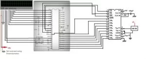
Project Circuit
The circuit of the project is not mush complex if you have taken the above tutorials. First insert 16×2 lcd, 89c51 and ADC0804 in your bread board. Make simple connections. Apply 5 volts to pin 40 and 31 of 89c51 microcontroller. Ground Pin 20. Connect Crystal(11.0592) to pin 18 and 19 of microcontroller in parallel to two 33pF capacitors. Connect reset button to pin 9 of 89c51 microccontroller. Connect Port-3 pin-0 to cs(chip select) of ADC0804, Port-3 pin-1 to wr pin of ADC0804, Port-3 pin-2 to rd pin of ADC0804, Port-3 pin-3 to intr pin of ADC0804. Port-3 pin-5 of 8051 to rs pin of 16×2 lcd, Port-3 pin-6 of 8051 to en pin of 16×2 lcd, make rw pin of 16×2 lcd ground. Apply 1.28 volts to vref/2 pin of ADC0804. This is the reference voltage for ADC0804. This is the voltage by which the step size of the ADC0804 will be set to 10 mv. LM35 output voltage varies 10 mV per °C change in temperature. Hence both the LM35 and ADC0804 are now working at 10 mv change. when there is 10 mv change in temperature the output Increments/decrements by 1.
To learn more about Lm35 temperature sensor working, pin out and formula to calculate temperature go through the below tutorial.
To learn more about Lm35 temperature sensor working, pin out and formula to calculate temperature go through the below tutorial.
At last connect Port-1 of 89c51 microcontroller with 8-bit output of ADC0804, and connect Port-2 with 8-bit input of 16×2 lcd. Circuit diagram of the project is given below.
ADC0804 with 8051(89c51,89c52) microcontroller CODE
Comming to the code first i included the header file reg51.h, you must include this header file in your every project in which you are using 8051(89c51,89c52) microcontroller. Then port three pins 5 and 6 are defined as rs(regester select) and en(enable) to be used for controlling lcd. If you dont know how to use 16×2 lcd then first take a small tutorial on
Port-3 pins 0, 1, 2 and 3 are used as cs(chip select) wr(write) rd(read) intr(interrupt) to control ADC0804. Project code is given below and each statement well explained.
| #include<reg51.h> | |
| sbit rs=P3^5; //Register select (RS) | |
| sbit en=P3^6; //Enable (EN) pin | |
| sbit cs=P3^0; | |
| sbit wr= P3^1; | |
| sbit rd= P3^2; | |
| sbit intr= P3^3; | |
| void delay(unsigned int time) //Time delay function | |
| { | |
| unsigned int i,j; | |
| for(i=0;i< time;i++) | |
| for(j=0;j<5;j++); | |
| } | |
| void lcdcmd(unsigned char value) //Function for sending values to the command register of LCD | |
| { | |
| P1=value; | |
| P3=0x40; | |
| delay(50); | |
| en=0; | |
| delay(50); | |
| return; | |
| } | |
| void display(unsigned char value) //Function for sending values to the data register of LCD | |
| { | |
| P1=value; | |
| P3=0x60; | |
| delay(500); | |
| en=0; | |
| delay(50); | |
| return; | |
| } | |
| void lcdint(void) //function to initialize the registers and pins of LCD | |
| { | |
| P1=0x00; | |
| P2=0x00; | |
| P3=0x00; | |
| delay(15000); | |
| display(0x30); | |
| delay(4500); | |
| display(0x30); | |
| delay(300); | |
| display(0x30); | |
| delay(650); | |
| lcdcmd(0x38); | |
| lcdcmd(0x0F); | |
| lcdcmd(0x01); | |
| lcdcmd(0x06); | |
| lcdcmd(0x80); | |
| } | |
| void main() | |
| { | |
| unsigned int Adcvalue,Adcvalue1; | |
| char ch1,ch2,ch3; | |
| P1=0x00; //Declared as Output port | |
| P3=0x00; //Output port | |
| P2=0xFF; //Input port | |
| lcdint(); | |
| while (1){ | |
| delay(10000); | |
| cs=0; //chipselect is on now –It is active low pin | |
| wr=0; // write is enabled –It is also active low | |
| delay(10); | |
| wr=1; //start conversion analog to digital | |
| rd=1; | |
| while(intr==1); //The looop runs until intr==1 and | |
| //when intr==0 it jumps to next iteration | |
| rd=0; //read the digital output from adc | |
| Adcvalue=P2; | |
| ch1=Adcvalue/100; | |
| if(ch1!=0) | |
| display(ch1+0x30); | |
| delay(100); | |
| Adcvalue1=Adcvalue%100; | |
| ch2=Adcvalue1/10; | |
| display(ch2+0x30); | |
| ch3=Adcvalue1-(ch2*10); | |
| display(ch3); | |
| delay(10000); | |
| lcdcmd(0x01); | |
| }} | |
 by
by More advance project on adc0804 is measure room temperature using 89c52 microcontroller, 16×2 lcd and adc0804. Tutorial contains free source code and circuit diagram of the project. Below button will take you to the project.
Download the project files and code(c,HEX) compiled in keil uvision 4. If you feel any problem in any statement or part of code just leave a comment below. Please give us your feed back on the Project.
Source: Prepaid Energy Meter with GSM Modem using pic microcontroller
- Why is an external device needed for 8051 microcontrollers?
Because 8051 microcontrollers do not have a built-in analog to digital converter. - What resolution does the ADC0804 provide?
It has an 8 bit resolution, meaning it can output a maximum value of 255 and a minimum of 0. - How is the reference voltage set in this project?
A voltage of 1.28 volts is applied to the vref/2 pin to set the step size to 10 mv. - Which pins control the ADC0804 operations?
Port-3 pins 0, 1, 2, and 3 are used as cs, wr, rd, and intr respectively. - How does the LM35 sensor relate to the ADC0804 settings?
The LM35 outputs 10 mV per degree Celsius, matching the 10 mV step size set by the ADC0804 reference voltage. - What header file must be included for 89c51 projects?
You must include the reg51.h header file. - Which port connects to the 8-bit output of the ADC0804?
Port-1 of the 89c51 microcontroller connects to the 8-bit output of the ADC0804. - What is the function of the reset button in the circuit?
The reset button is connected to pin 9 of the 89c51 microcontroller.