A microcontroller is a small computer which fits on a single chip. Like other computers, the microcontroller follows a sequence of instructions, one at a time, to carry out a program. With the help of a microcontroller we are going to make a morse code flasher which flashes FSC.
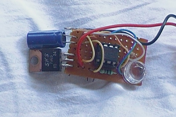
Step 1: Materials Required
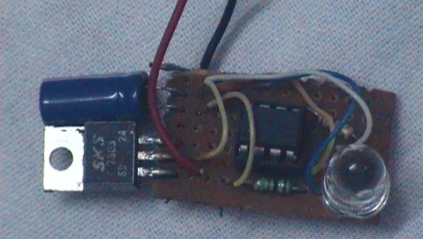
the things required are:
1] 10k ohm resistor
2] 470 ohm resistor
3] 0.1 uf capacitor
4] 1000 uf capacitor
5] 5V regulator
6] LED
7] PIC12F683
8] Bread board for prototyping and a strip board for soldering
Step 2: Schematic!!!!
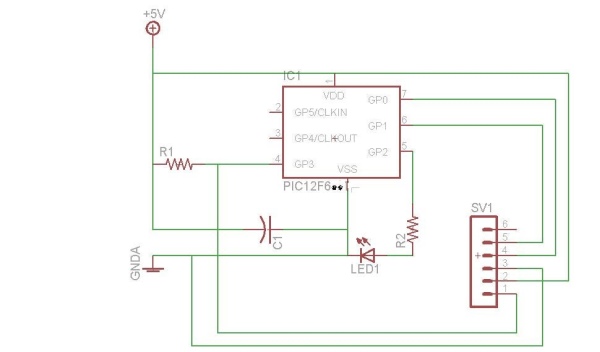
This circuit uses the PIC 12F683, as the controller. Not shown in the schematic is the voltage regulator and battery clip/battery. There is an additional resistor, with a value of 10KΩ ; it is labeled R1 in the schematic. It has brown, black, orange, and gold bands on it, standing for 1, 0, three zeros, and 5%, respectively. This is quite a bit more resistance than the R2 resistor, which is 470 Ω, so don’t mix them up. C1 should be .1μFarad.
The schematic looks quite complicated. The LED and 470Ω resistor are turned around, though. In this circuit the positive side of the LED connects to the PIC12F683 and the negative side of the LED connects to the resistor. The resistor connects to ground, instead of the positive bus.
If you are externally programming the chip no need of the programming header.
Step 3: Making the Circuit
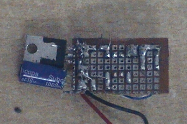
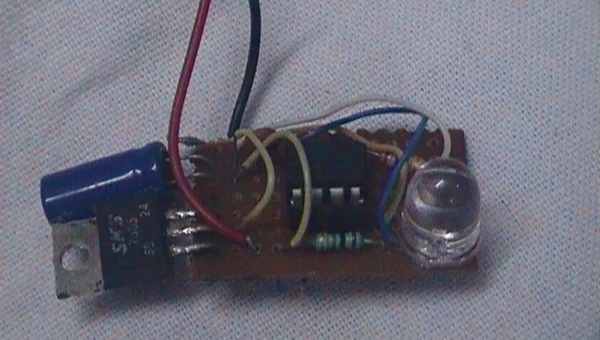
First use a breadboard to prototype and test the circuit and then solder all the components on the pref board.
Step 4: Setting Up the Software
Before we can actually use this circuit, we need to set up the program on the microcontroller, and before we can do that, we need to install the appropriate software in the PC. The software we will install is:
+GPASM — which you can probably run directly from the folder on the USB drive.
+PICKit 2 software, which is also on the USB drive
+Also on the USB drive, but which we will not use today, is the CC5X compiler for writing programs in the C language instead of assembler. Many people prefer this option.
Step 5: The Code Explained
Morse code is explained in the following comment, which appears in the code:
; Morse code consists of
; dots, which are short blinks;
; dashes, which are long blinks, three times as long as a dot;
; and spacings, which are periods in which the light is off.
; spacings come in various lengths:
; Within a letter, dots and dashes are separated by a
; spacing which is the same length as a dot.
; letters are separated by a spacing the same length as a dash.
; And words are separated by a spacing five times as long as a dot.
;
; The code: (More or less. It’s a long time since Boy Scouts)
; A .- * B -… * C -.-. * D -..
; E . * F ..-. * G –. * H ….
; I .-. * J .— * K -.- * L .-..
; M — * N -. * O — * P .–.
; Q –.- * R .-. * S … * T –
; U ..- * V …- * W .– * X -..-
; Y -.– * Z –..
;
;
Comments in PIC Assembly Language (which is the language in which this program is written) start with a semi-colon character, and continue to the end of the line. Comments are intended for the next person who works on the code, and do not actually give any instructions to the microcontroller. So this table of Morse code letter values doesn’t tell the computer anything. The instructions to the computer appear further down.
When the microcontroller starts up, it begins going through the instructions beginning at location zero. In this program, the instructions beginning at line 45 will be placed at location zero, because of the org 0 on line 44. (In notepad, you can find numbered lines by pulling down the Edit menu and clicking Goto Line. Notepad disables Goto Line if wordwrap is enabled; if Goto Line doesn’t seem to work (is grayed out) pull down the Format menu, and unclick wordwrap.)
org 0 ; reset vector
Start:
goto main
org 4 ; interrupt vector
retfie ; do nothing
main:
banksel TRISIO ;select bank 1, where TRISIO is stored.
movlw 0 ;set GP0-GP5 all outputs.
movwf TRISIO
banksel GPIO ;select bank 0, to use GPIO
bcf GPIO,2; ;; turn off LED
loop:
call letterF
call S
call letterC
call spacing
goto loop
The bit about TRISIO is initialization to set up the microcontroller. To understand it completely, you’d need to read through the datasheet for the PIC12F683.
The program goes through the instruction on each line, then moves to the next line, unless the instruction is a goto, call, return, or retfie
It is logical to conclude that the line call letterF causes the microcontroller to flash an F in Morse code. It is also true, but the reason is is true is that a block of code named letterF() has already been defined in this program. That block looks like this:
; The code for F is ..-.
letterF:
call dot
call dot
call dash
call dot
call spacing
return
Since the table of letters tells us that the letter F is ..-. it is again logical to believe that that is what this code does — tells the microcontroller to first flash a dot, then a dot, then a dash, etc. Again, it is also true, but again, because we have appropriate code elsewhere in the program. For example, we have:
dot:
bsf GPIO,2; ;; turn on LED
call dotTime; ;; wait a bit
bcf GPIO,2; ;; turn off LED
call dotTime; ;; wait a bit
return
The colon suggests that this is the definition of dot; that’s correct, and only one definition is allowed for a symbol in a program. We can use it as often as we want, though.
To make sense of this we need to know that GPIO bit 2 is connected to pin 5, which is where we connected the LED. When GPIO bit 2 is set to 1, pin 5 has 5 volts on it. When we send the value 0 to GPIO pin 2, the voltage on the pin changes to 0 volts. The names of the pins on the circuit schematic hint at this.
So a dot is flashed by turning the LED on, waiting awhile, then turning it off and waiting awhile. We need a wait after the dot to keep the flashes from running unreadably together, and that is what the dotTime code does.
The names of the various PIC12F683 pins and registers are hidden inside a file which we include at the top of the program in the line
#include <p12F683.H>
The dotTime block looks like this
dotTime:
call delay; ;; wait a bit
return
delay is yet another block of code, probably the most complicated in this program:
;define program variables. These happen to be in bank 0
i equ 0x20
j equ 0x21
k equ 0x22
delay: ;delays~ 1 second on a 4MHz clock
movlw 5
movwf i ;uses a triply nested loop
topi: clrf j
topj: clrf k
topk: incfsz k,1 ;count to 256
goto topk ;inner loop is 3 cycles
incfsz j,1
goto topj
decfsz i,1
goto topi
return
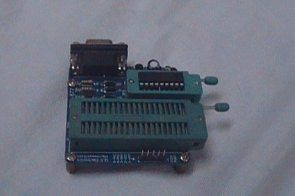
you would need a programmer to program the code into the chip.
Attachments
Step 6: Find a Case and Install the Circuit in It

Install the circuit in a box i chose a medicine box as my mom is a doctor so i have hundreds of medicine boxes laying around. Or just create it with the help of cardboard if u get no box of appropriate
Step 7: Action Time
Source: Pocket Sized Morse Code Flasher
