Summary of PICMICRO LED TACHOMETER CIRCUIT
This article describes a DIY digital tachometer using PIC16F874 or PIC16F877 microcontrollers. It converts an analog instrument into a digital display with 33 LED segments, measuring speeds from 0 to 8000+ rpm in 250 rpm increments. The circuit uses a 20MHz clock and connects via four cables: power, ground, clock, and backlight.
Parts used in the PICmicro LED Tachometer:
- PIC16F874 microcontroller
- PIC16F877 microcontroller
- 33-hole LEDs PCB layout
- Analog bargraph LEDs
- Divider resistors
- Zündspulenunterbrecher (ignition coil interrupter)
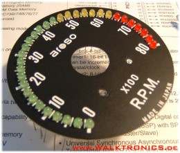
Handmade pretty stylish LED display digital speedometer tacho meters. Source or assembly code pic16f874 PIC16F877 can be done with the circuit and wiring diagrams directly from the preparation given the 33-hole leds pcb layout on a plaque made analog… Electronics Projects, PICmicro LED tachometer Circuit “led projects, microchip projects, microcontroller projects,
Handmade pretty stylish LED display digital speedometer tacho meters. Source or assembly code pic16f874 PIC16F877 can be done with the circuit and wiring diagrams directly from the preparation given the 33-hole leds pcb layout on a plaque made
analog instrument into a digital tachometer with analog bargraph LEDs. The meter can measure and display a speed range from 0 rpm to 8000 rpm and higher in 250’er increments. Intermediate values are indicated by a pulse-pause ratio of the next higher LED. This is admittedly a bit of getting used to when it flashes in the view, but can be improved in the software.
LED TACHOMETER CIRCUIT
The LED tachometer is based on the PIC 16F874/877 which can control the LEDs directly with its wealth of I / O pins and makes the overall circuit is therefore very simple.
Was programmed the circuit for a 4-cylinder gasoline engine. The speed is measured directly or via divider resistors at Zündspulenunterbrecher. Configured the PIC on a clock frequency of 20MHz. There were all port pins except PORTA, 0 used as LED pins. The circuit is connected to a total of 4 cables. (+ Ub, GND, CLOCK, backlight).
FILE DOWNLOAD LINK LIST (in TXT format): LINKS-7897.zip
Source: PICMICRO LED TACHOMETER CIRCUIT
- Which microcontrollers are used for this project?
The project uses the PIC16F874 or PIC16F877 microcontrollers. - What speed range can this tachometer measure?
It measures speeds from 0 rpm to 8000 rpm and higher. - How are intermediate values displayed on the meter?
Intermediate values are indicated by a pulse-pause ratio of the next higher LED. - What is the configured clock frequency for the PIC?
The PIC is configured on a clock frequency of 20MHz. - How many cables connect the circuit?
The circuit is connected to a total of 4 cables. - Which ports are used as LED pins?
All port pins except PORTA, 0 are used as LED pins. - Can source code be obtained for this project?
Yes, source or assembly code is available for download.