Summary of PICKit3 Programming With MPLABX
This article describes building a minimal PIC 18F452 programming circuit and using Microchip MPLABX with the C18 compiler and a PICKit3 programmer to load a simple LED-flashing program. It covers required parts, basic schematic (power via 7805, MCLR pull-up, ICSP connection), and using RA1 for an LED output to verify programming.
Parts used in the PICKit3 Programming Project:
- PICKit3
- PIC 18F452
- 7805 +5v Regulator
- 20 MHz Crystal
- 10kΩ Resistor
- 1uF Capacitor
- 5mm LED
- Breadboard
- Breadboard Wire
- SIPs
- 9v Connector
- Battery Holder
The PICKit3 is microchip’s newest official PIC programmer and while people argue about how good it is, this programmer has never done me wrong. I upgraded away from the old ICD2 clone programmer that I had used for years when I saw that microchip sells their PICKit3 for under $50 and so now I’ll pass on my experience of how to use it, to you guys!
In this article I will explain the process of building up the basic PIC circuit, enough for it to be programmed, and then I will show you how MPLABX and the C18 Compiler is used with the PICKit3 to program the PIC microcontroller, using a simple LED flashing program.
Purpose & Overview of this project
The goal of this project is to install an IDE suite for writing our programs, install a compiler for that IDE suite and to build the minimum hardware circuit necessary for loading programs onto the microcontroller.
We will use microchip’s MPLABX combined with microchip’s C18 Compiler to compile our firmware program and then load it onto a PIC. The PIC we’ll use for this project is the generic 18F452.
PIC 18F452
7805 +5v Regulator
20 MHz Crystal
10kΩ Resistor
1uF Capacitor
5mm LED
Breadboard
Breadboard Wire
SIPs
9v Connector
Battery Holder
Parts List Details
You are probably familiar with most of the parts listed out above, but if that’s not the case-don’t fear! I will briefly explain the purpose of the most important parts in the sections below.
PICKit3
The focus of this article is using the PICKit3 to program the PIC. The PICKit3 is microchip’s newest programmer for loading programs onto the many different version of the 12xx, 16xx, 18xx, 24xx, 32xx and other series of PICs that microchip manufactures, so getting a PICKit3 is a one-time cost and great investment.
PIC 18F452
The PIC 18F452 is a fairly generic and widely available microcontroller. I have used it in many, many of my articles and projects so after you master programming the PIC using a PICKit3 you can try your hand and building similar projects like mine.
7805 +5v Regulator
This component is used to regulate the +9v or larger that comes from the power supply or battery that I’m using down to the +5v that the PIC needs to have.
20 MHz Crystal
I chose 20 MHz semi-randomly, any crystal 4 MHz or higher will work for this article. This will act as the clock speed with the PIC instruction speed being 20 / 4 = 5 MHz, because it takes 4 clock cycles to execute 1 PIC instruction.
Breadboard and Breadboard Wire
The breadboard will serve as our platform for connecting everything together and the breadboard wire is what we’ll use to actually connect everything together.
9v Connector
Since most people don’t have dedicated power supplies for hobby electronics, I find it is typically easier to use a battery like a +9v or a battery back, so this connector makes it easy to bring power and ground through the red/black wires to the breadboard.
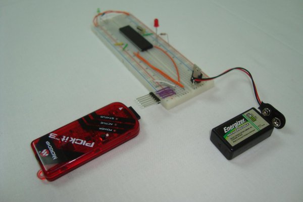
Schematic Overview
The schematic for this project is the basic PIC programming circuit. Many safety components that a professional designer would add to the circuit have been deleted to make the circuit as simple as possible. Since we’re doing simple hobby electronics this doesn’t really make a difference. The main parts in the schematic are the PICKit3, PIC 18F452 and 7805.
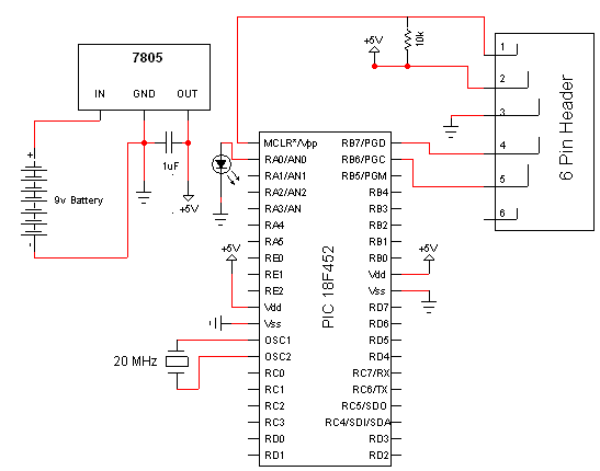
Schematic Specifics
Power Regulator
The 7805 converts the input +9v down to a +5v output which powers the PIC. The PIC has two spots where it connects to power and ground, and there is a single 10kΩ resistor connected to the MCLR Pin1 of the pic that goes to power.
ICSP connection
ICSP is short for in-circuit serial programmer and this is the port used on almost every PIC microcontroller to load your program onto it. The PICKit3 has the same pinout as the connector seen above, the little dot on the PICKit3 tells you which connection is PIN1 or MCLR.
LED Output
A single led can be seen off of PORTA RA1 or PIN2 on the PIC. This led will be used to confirm that out program was successfully loaded onto the PIC by flashing on and off at a predetermined speed.
For more detail: PICKit3 Programming With MPLABX
- What is the purpose of this project?
To install an IDE and compiler and build the minimum hardware circuit to load programs onto a PIC 18F452 using MPLABX, the C18 compiler, and a PICKit3. - Can I use a PICKit3 to program the PIC 18F452?
Yes, the PICKit3 is used to load programs onto the PIC 18F452 via the ICSP port. - What power supply arrangement is used for the PIC?
A 7805 regulator converts a +9v battery input down to +5v to power the PIC. - How is the PIC held in reset?
A single 10kΩ resistor is connected to the MCLR pin and tied to +5v as a pull-up. - Which pin is used for the LED output in the example?
The LED is connected to PORTA RA1 (PIN2) to flash and verify programming. - What clock speed is used for the PIC in this project?
A 20 MHz crystal is used, giving an instruction speed of 20/4 = 5 MHz. - Does the PICKit3 pinout match the ICSP connector on the PIC?
Yes, the PICKit3 has the same pinout as the ICSP connector and a dot marks PICKit3 PIN1 (MCLR). - Are safety components included in the schematic?
No, many professional safety components were omitted to keep the circuit simple for hobby use.