Summary of PIC18Fxxx DC Servomotor using PIC18F452 with Proteus Simulation
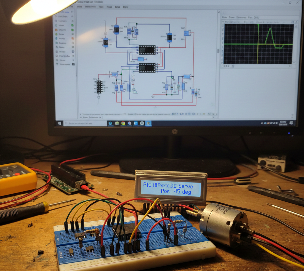
This project implements a PID-based closed-loop DC servomotor control system on a PIC18F452, featuring trapezoidal motion profiling, encoder feedback, RS232 command/tuning, EEPROM storage, and Proteus VSM simulation for development and testing.
Parts used in the PIC18F452 DC Servomotor Project:
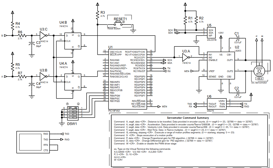
- PIC18F452 Microcontroller
- DC Servomotor
- Motor Driver IC (PWM controlled)
- Incremental Encoder
- External I2C EEPROM (24C01)
- RS232 Interface (USART)
- Power Supply (24V motor, 5V logic)
- Discrete components (resistors, capacitors, switches)
- Can this project run fully in Proteus simulation?
Yes, the complete system is designed for Proteus VSM testing. - Which PIC microcontrollers are compatible?
PIC18Fxxx devices with PWM, timers, and USART support are suitable. - How is motor position feedback implemented?
Using encoder pulses counted by Timer0 and Timer1. - Can PID parameters be changed during runtime?
Yes, via RS232 commands and stored in EEPROM. - What motion profile is used?
Trapezoidal motion profile with acceleration, velocity limit, and deceleration. - What baud rate does RS232 use?
19200 baud at 20 MHz system clock. - Is this suitable for real hardware deployment?
Yes, the design closely matches industrial servo control principles. - Can this be modified for stepper motors?
The control logic would require changes, but the framework is reusable.