AN245 – MCP23016 Interfacing using PIC16F877A with Proteus Simulation

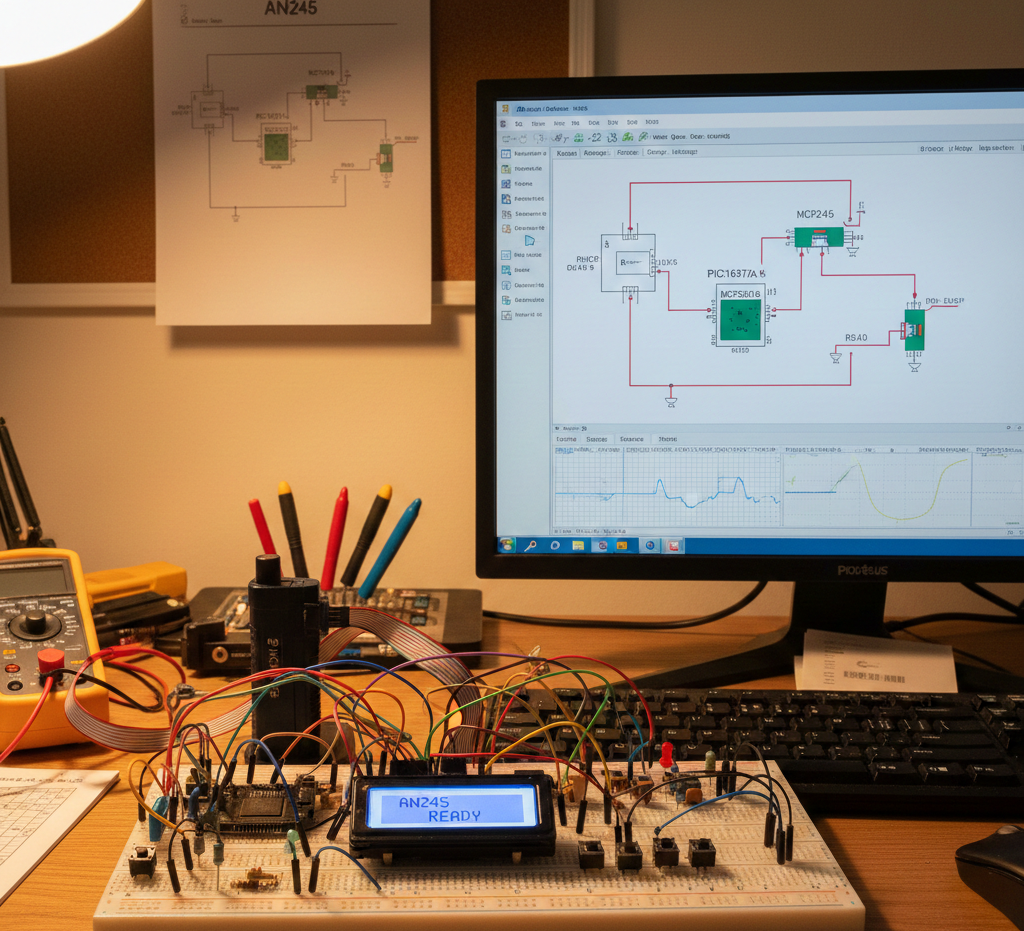
Summary of AN245 – MCP23016 Interfacing using PIC16F877A with Proteus Simulation


This project demonstrates interfacing the Microchip MCP23016 16-bit I/O expander with a PIC16F877A over hardware I²C, using Proteus VSM for simulation. It implements LED chaser output, interrupt-driven input monitoring via CCP2, bidirectional GPIO mirroring, and modular XC8/HI-TEC firmware (I²C driver, read/write routines, ISR), illustrating practical I/O expansion, interrupt handling, and firmware–hardware integration.

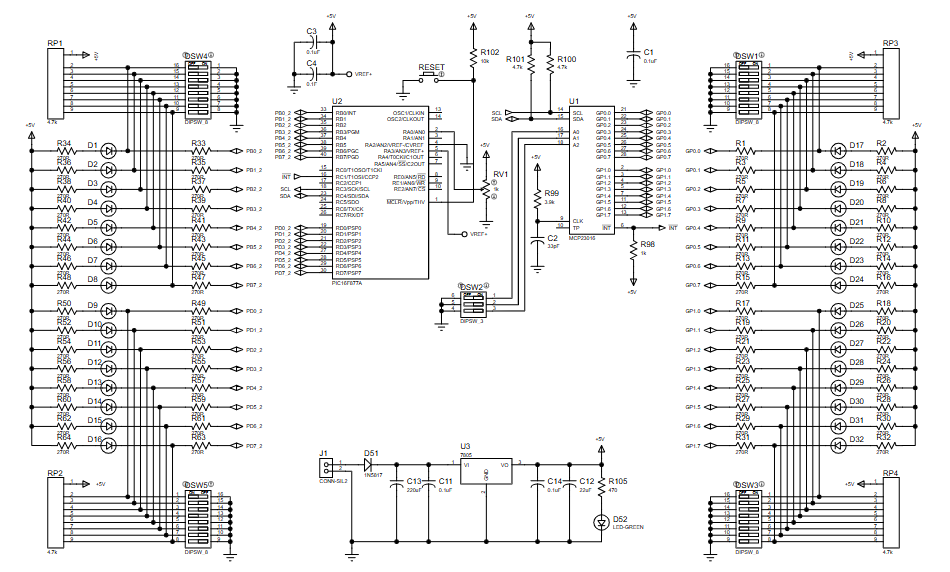
Parts used in the MCP23016 PIC16F877A Interfacing Project:

  • PIC16F877A microcontroller
  • MCP23016 16-bit I/O expander
  • LEDs (16 channels)
  • Push switches (16 channels)
  • Pull-up resistors
  • Crystal oscillator
  • Power supply circuitry
  • Proteus VSM simulation environment

Introduction

Interfacing external I/O expanders is a common requirement in embedded systems when microcontroller pins are limited. This microcontroller project demonstrates how to interface the Microchip MCP23016 I/O Expander with a PIC16F877A using the I²C protocol, fully tested in Proteus simulation.
Based on Microchip Application Note AN245, the project shows practical read/write operations, interrupt handling, and LED control using an external I/O device. It is a solid example of practical electronics, firmware-driven peripherals, and I²C-based expansion for PIC microcontrollers.MCP23016 PIC16F877A interfacing is demonstrated in this project using the I²C protocol to expand GPIO capability, verified through Proteus simulation with interrupt-driven input and output control.MCP23016 PIC16F877A interfacing is the focus of this project, demonstrating GPIO expansion using the I²C protocol with interrupt-driven input and output control verified in Proteus simulation.

Embedded I²C lab prototype setup
Illustrative View of the Concept.

How the Project Works (Overview)

The PIC16F877A communicates with the MCP23016 over hardware I²C. The MCP23016 provides 16 additional digital I/O pins, split into LSB and MSB ports.
The firmware continuously writes LED patterns to the expander while also monitoring interrupt signals. When a change is detected on the MCP23016 inputs, the PIC reads back the port states and updates its own output ports accordingly. This allows simultaneous output control and input monitoring using the same external pins.

Block Diagram / Workflow Explanation

  1. PIC16F877A initializes I²C, CCP2 interrupt module, and GPIO ports

  2. MCP23016 is configured as a 16-bit output device

  3. PIC writes LED chase patterns to MCP23016 output latches

  4. MCP23016 triggers an interrupt on input change

  5. PIC interrupt service routine sets a software flag

  6. PIC reads MCP23016 input registers via I²C

  7. Data is mirrored on PIC PORTB and PORTD

Key Features

  • I²C-based I/O expansion using MCP23016

  • Hardware I²C implementation on PIC16F877A

  • 16-channel LED chaser demonstration

  • Interrupt-driven input monitoring

  • Active-low output configuration

  • Fully simulated and testable in Proteus VSM

Components Used

  • PIC16F877A microcontroller

  • MCP23016 16-bit I/O expander

  • LEDs (16 channels)

  • Push switches (16 channels)

  • Pull-up resistors

  • Crystal oscillator

  • Power supply circuitry

  • Proteus VSM simulation environment

Applications

  • Expanding GPIO pins in PIC-based systems

  • LED matrices and display drivers

  • Industrial control panels

  • Input/output monitoring systems

  • Educational I²C and interrupt handling labs

  • Embedded system prototyping

Explanation of Code (High-Level)

The firmware is written for the HI-TEC / MPLAB XC8 compiler.
Key software modules include:

  • I²C Driver (i2crxtx.c)
    Handles start, stop, read, write, and repeated-start conditions.

  • MCP23016 Write Function
    Sends two bytes (LSB & MSB) to the output latch registers.

  • MCP23016 Read Routine
    Reads input states using I²C repeated-start mode.

  • Interrupt Service Routine (ISR)
    Uses CCP2 capture interrupt to detect MCP23016 activity.

  • Main Loop
    Generates a bidirectional LED chaser pattern while continuously checking for input interrupts.

No line-by-line logic is required to understand the system—the project focuses on working principle, modular firmware, and hardware interaction.

Source Code

Download
 /*===========================================================================
 Written in HI-TEC PIC C COMPILER By Abdelwahab Fassi-Fihri

 this program is using the hardware i2c on the pic 16f877A to read from

 and write to the Microchip MCP23016 I/O Expander.

=\=\=\=\=\=\=\=\=\=\=\=\=\=\=\=\=\=\=\=\=\=\=\=\=\=\=\=\=\=\=\=\=\=\=\=\=\=\=\
This is to test with 16 leds and 16 switchs on same pins with interupt.
=\=\=\=\=\=\=\=\=\=\=\=\=\=\=\=\=\=\=\=\=\=\=\=\=\=\=\=\=\=\=\=\=\=\=\=\=\=\=\

Proteus Simulation

In Proteus VSM, the simulation shows LEDs connected to the MCP23016 turning ON sequentially in a chaser pattern.
When switches are toggled, the MCP23016 generates an interrupt, triggering the PIC to read back the new input state. The system responds in real time, confirming correct I²C communication, interrupt handling, and firmware logic.

(FAQs)

1. Why use MCP23016 instead of direct GPIO?

It expands I/O capability without changing the microcontroller.

2. Can this work with other PIC16 devices?

Yes, any PIC with hardware I²C support can be adapted.

3. Why are outputs inverted in the code?

The test board uses active-low LED configuration.

4. Does this work in Proteus without hardware changes?

Yes, the project is fully compatible with Proteus simulation.

5. Can inputs and outputs be mixed on MCP23016?

Yes, via the I/O direction registers.

6. What triggers the interrupt?

Input state changes on MCP23016 monitored through CCP2.

7. Can XC8 replace HI-TEC compiler?

Yes, with minor syntax adjustments.

8. Is polling possible instead of interrupts?

Yes, but interrupts are more efficient.

Conclusion

This project is a clean and practical demonstration of I²C-based I/O expansion using the PIC16F877A and MCP23016. It combines firmware design, interrupts, and external peripherals into a single Proteus simulation.
For learners exploring embedded systems, DIY electronics, and real-world microcontroller interfacing, this application note–based project delivers strong educational value with real hardware relevance.

Quick Solutions to Questions related to MCP23016 PIC16F877A Interfacing Project:

  • Why use MCP23016 instead of direct GPIO?
    It expands I/O capability without changing the microcontroller.
  • Can this work with other PIC16 devices?
    Yes, any PIC with hardware I²C support can be adapted.
  • Why are outputs inverted in the code?
    The test board uses active-low LED configuration.
  • Does this work in Proteus without hardware changes?
    Yes, the project is fully compatible with Proteus simulation.
  • Can inputs and outputs be mixed on MCP23016?
    Yes, via the I/O direction registers.
  • What triggers the interrupt?
    Input state changes on MCP23016 monitored through CCP2.
  • Can XC8 replace HI-TEC compiler?
    Yes, with minor syntax adjustments.
  • Is polling possible instead of interrupts?
    Yes, but interrupts are more efficient.

About The Author

Ibrar Ayyub

I am an experienced technical writer holding a Master's degree in computer science from BZU Multan, Pakistan University. With a background spanning various industries, particularly in home automation and engineering, I have honed my skills in crafting clear and concise content. Proficient in leveraging infographics and diagrams, I strive to simplify complex concepts for readers. My strength lies in thorough research and presenting information in a structured and logical format.

Follow Us:
LinkedinTwitter