Brushless Motor Control Made Easy using PIC16F877 with Proteus Simulation

Summary of Brushless Motor Control Made Easy using PIC16F877 with Proteus Simulation


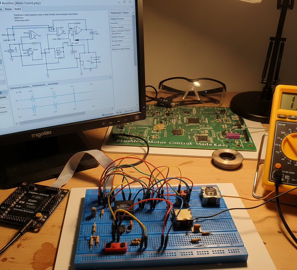
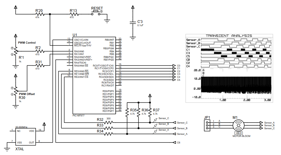
Brushless DC motor control using a PIC16F877 is demonstrated via sensor-based commutation and PWM speed/offset control, implemented and tested entirely in Proteus VSM. The MPASM firmware reads three rotor position sensors to sequence three-phase outputs, enabling realistic simulation of BLDC behavior for learning and prototyping based on AN857.

Parts used in the Brushless Motor Control Made Easy using PIC16F877 with Proteus Simulation:

  • PIC16F877 microcontroller
  • Brushless DC motor (BLDC)
  • Rotor position sensors (A, B, C)
  • PWM control potentiometers
  • Crystal oscillator
  • Resistors
  • Capacitors
  • Reset circuitry
  • Power supply connections

Introduction

Brushless DC (BLDC) motors are widely used in modern electronics due to their efficiency and reliability.
This microcontroller project demonstrates how BLDC motor control can be simplified using a PIC16F877 and sensor-based commutation.
Based on Application Note AN857, the project shows a practical motor control approach implemented and tested entirely in Proteus simulation.
It is an excellent example of applying embedded systems concepts to real-world motor control.
The project is especially useful for learners exploring DIY electronics, PWM control, and sensor feedback techniques.

BLDC motor control hardware test setup
Illustrative View of the Concept.

How the Project Works (Overview)

The system controls a brushless DC motor using sensor inputs that indicate rotor position.
The PIC16F877 reads three sensor signals and generates appropriate PWM-driven control outputs.
These outputs drive the motor phases in the correct sequence, ensuring smooth rotation.
PWM control and offset inputs allow speed and timing adjustments.
All logic and timing are handled in firmware written using MPASM and verified through Proteus VSM.

Block Diagram / Workflow Explanation

  1. Sensor Inputs (A, B, C)
    Three motor position sensors feed digital signals into the PIC16F877.

  2. Microcontroller Processing
    The PIC analyzes sensor states and determines the correct commutation sequence.

  3. PWM Control Logic
    PWM control and offset inputs adjust duty cycle and motor response.

  4. Motor Drive Outputs
    The controller drives three motor phases based on calculated timing.

  5. BLDC Motor Operation
    Correct phase switching results in continuous and controlled motor rotation.

Key Features

  • Sensor-based BLDC motor commutation

  • PWM speed and offset control

  • PIC16F877-based motor control firmware

  • Fully simulated using Proteus VSM

  • Application-note-driven reference design

  • Clear phase sequencing for reliable motor operation

Components Used

  • PIC16F877 microcontroller

  • Brushless DC motor

  • Rotor position sensors (A, B, C)

  • PWM control potentiometers

  • Crystal oscillator

  • Resistors and capacitors

  • Reset circuitry

  • Power supply connections

Applications

  • Brushless motor controllers

  • Robotics and automation systems

  • Embedded motor control learning projects

  • Industrial control training setups

  • Educational simulation-based electronics labs

Explanation of Code (High-Level)

The firmware is written in MPASM and focuses on sensor-driven motor control.
It continuously monitors three sensor inputs to detect rotor position.
Based on sensor states, the code selects the correct output pattern for motor commutation.
PWM routines adjust motor speed and timing offsets.
The firmware is optimized for simulation and demonstration rather than hardware-specific drivers.

Source Code

Download
Define I/O
;*

#define	OffMask		B'11010101'
#define	DrivePort	PORTC
#define DrivePortTris	TRISC
#define	SensorMask	B'00000111'
#define	SensorPort	PORTE
#define DirectionBit	PORTA,1

Proteus Simulation

In Proteus VSM, the circuit simulates real-time motor behavior.
Sensor waveforms change dynamically, and PWM signals adjust motor response.
The BLDC motor model responds to phase switching accurately.
Transient analysis confirms correct timing and phase relationships.
This makes the project ideal for testing without physical hardware.

(FAQs)

1. Can this project run entirely in Proteus?

Yes, the design is specifically intended for Proteus simulation using VSM.

2. Which microcontroller is used?

The project uses the PIC16F877 from the PIC16 family.

3. Is this sensor-based or sensorless control?

This is a sensor-based BLDC motor control project.

4. What compiler is required?

The firmware is written using MPASM.

5. Can PWM values be modified?

Yes, PWM control and offset inputs allow adjustment.

6. Is this suitable for beginners?

Yes, it is ideal for learning motor control fundamentals.

7. Can the design be extended to hardware?

Yes, the simulation can be adapted to real hardware with appropriate drivers.

8. What is the main learning focus?

Understanding BLDC commutation, PWM control, and embedded motor logic.

Conclusion

This project demonstrates how brushless motor control can be simplified using a PIC microcontroller.
By combining sensor feedback, PWM control, and Proteus simulation, it provides strong hands-on learning value.
It is an excellent reference for students and engineers exploring embedded systems and motor control.
AN857 serves as a solid foundation for building more advanced BLDC applications.

Quick Solutions to Questions related to Brushless Motor Control Made Easy using PIC16F877 with Proteus Simulation:

  • Can this project run entirely in Proteus?
    Yes, the design is specifically intended for Proteus simulation using VSM.
  • Which microcontroller is used?
    The project uses the PIC16F877 from the PIC16 family.
  • Is this sensor-based or sensorless control?
    This is a sensor-based BLDC motor control project.
  • What compiler is required?
    The firmware is written using MPASM.
  • Can PWM values be modified?
    Yes, PWM control and offset inputs allow adjustment.
  • Is this suitable for beginners?
    Yes, it is ideal for learning motor control fundamentals.
  • Can the design be extended to hardware?
    Yes, the simulation can be adapted to real hardware with appropriate drivers.
  • What is the main learning focus?
    Understanding BLDC commutation, PWM control, and embedded motor logic.

About The Author

Ibrar Ayyub

I am an experienced technical writer holding a Master's degree in computer science from BZU Multan, Pakistan University. With a background spanning various industries, particularly in home automation and engineering, I have honed my skills in crafting clear and concise content. Proficient in leveraging infographics and diagrams, I strive to simplify complex concepts for readers. My strength lies in thorough research and presenting information in a structured and logical format.

Follow Us:
LinkedinTwitter