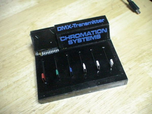
PIC18F Based 6 Channel DMX Transmitter
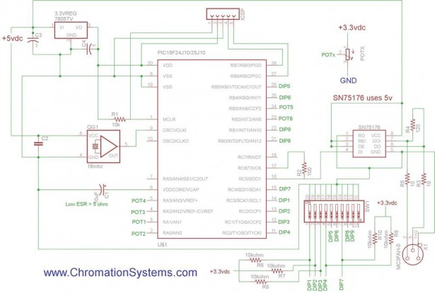
It is written in Assembly and utilizes a PIC18F24J10. A bit odd as it’s voltage input is 3.3v and it requires a low ESR capacitor to ground on one of its pins. I am sure the code could be modified to work on any 18F PIC with a EUSART.
There is no PCB layout, it is easy enough to construct point to point on perfboard.
Please Take a look at AN1076 From Microchip and the PIC18F24J10 Datasheet.
I apologize about my images as my camera decided to crap out with this and another project worth of images on it, so I did my best to recover and recreate them.
*UPDATE:
V2 – Updated the schematic to show the potentiometer hookup.
V3 – PIC Transmit pin was hooked up to the wrong pin on the SN75176, fixed, should be pin 16 on the PIC connected to pin 4 on the transceiver. A pretty big mistake, sorry to anyone that got screwed up by it.
DISCLAIMER: Not responsible for any damage or injuries resulting from this instructable. Damage to DMX Devices is possible if this transmitter is not built correctly.
Supplies
– 18F24J10
– SN75176A – RS-485 differential bus transceiver
– 28 pin socket
– 8 pin socket
– 10 position DIP Switch
– 3.3v linear regulator, TO-220
– 16 mhz Crystal Oscillator – I used ECS-2200BX-160
– 8 pin socket
– 28 pin socket
– 6x slide or dial Potentiometers
– Female XLR, i use panel mount
– Male XLR, not really needed
– 2x 10 1/4w resistor, R3 & R5
– 100 ohm 1/4w resistor, R2
– 120 ohm 1/4w resistor, R4
– 10kohm 1/4w resistor, R1
– 10uF low ESR cap, less than 5 ohm, but most caps can still work,C1
– 2x 1uF electrolytic capacitor, C3 & C4
– 0.1uF disc capacitor, C2
– Perfboard
– Solid strand wire
– 5v @ 500ma PSU
– DC Power Jack, I used a 2.1mm that matched my 5v power supply. Buy PSU with Matching Jack
-Enclosure, or parts to build one. Tools:
– Solder
– Soldering Iron
– Pliars
– Diagnal Cutter
Layout the Board
I don’t think my layout is optimal. The DIP switch is in an awkward spot which caused a bit of problems when building the enclosure. But overall it is quite small, which was the idea.
Start Point to Point

Make sure that the potentiometer have their voltage hooked up right so the correct direction is value up or down. In my case the pot’s contacts on the bottom of the board was hooked to negative and other end to positive, so when the pots were slid upwards towards the PIC, it increased the DMX value. I did it wrong first and had to go back and fix it. The pot’s center should be connected to the PIC pin, the other to 3.3v(not 5v) and ground.- The Oscillator and the SN75176 require a 5v input and the PIC requires 3.3v.
– Most 3.3v regulators have a different pinout than a 7805, so make sure and find out.
– The male XLR receptacle is not required or is the ICSP jack.

